High voltage switch triggered by a laser-photocathode subsystem

a laser-photocathode subsystem and high-voltage switch technology, which is applied in the direction of spark gap details, discharge tube main electrodes, gas-filled discharge tubes, etc., can solve the problems of laser-triggered switches, waste optical energy, and delay and jitter of breakdown induced by this method, so as to achieve less breakdown delay and jitter, and operate reliably, simple and easy-to-use effects

Inactive Publication Date: 2011-09-08
DULY RES
View PDF3 Cites 10 Cited by
  • Summary
  • Abstract
  • Description
  • Claims
  • Application Information

AI Technical Summary

Benefits of technology

[0010]The present invention incorporates the advantages of the electrically triggered spark gap switches, which are relatively simple and easy to operate, with the merits of the laser triggered spark gap switches, which have less breakdown delay and jitter and which can be decoupled from the main switching circuit. It provides a high voltage switch that can be operated reliably through a double triggering mechanism. Such a switch will make use of the laser optical energy more efficiently.

Problems solved by technology

For example, the electrical pulse triggered switch is comparably simple, but it needs a separate electrical pulse generator, and the delay and jitter of the breakdown induced by this method are relatively larger.
Though great progress has been made, some problems remain for the laser-triggered switches.
Therefore, most of photons in the laser beam passing through a common gas gap whose length is generally less than 30 cm simply waste their optical energy.
For this reason, a high-energy laser system is needed to trigger a traditional high voltage spark gap switch, thus incurring a very high cost for the laser system.
Otherwise, the delay time and the jitter of the switch will be adversely impacted.
The lifetimes of the photoemission materials are also limited.
Furthermore, the medium in such switches can only be gases.

Method used


Image

  • High voltage switch triggered by a laser-photocathode subsystem
  • High voltage switch triggered by a laser-photocathode subsystem
  • High voltage switch triggered by a laser-photocathode subsystem

Examples


Embodiment Construction

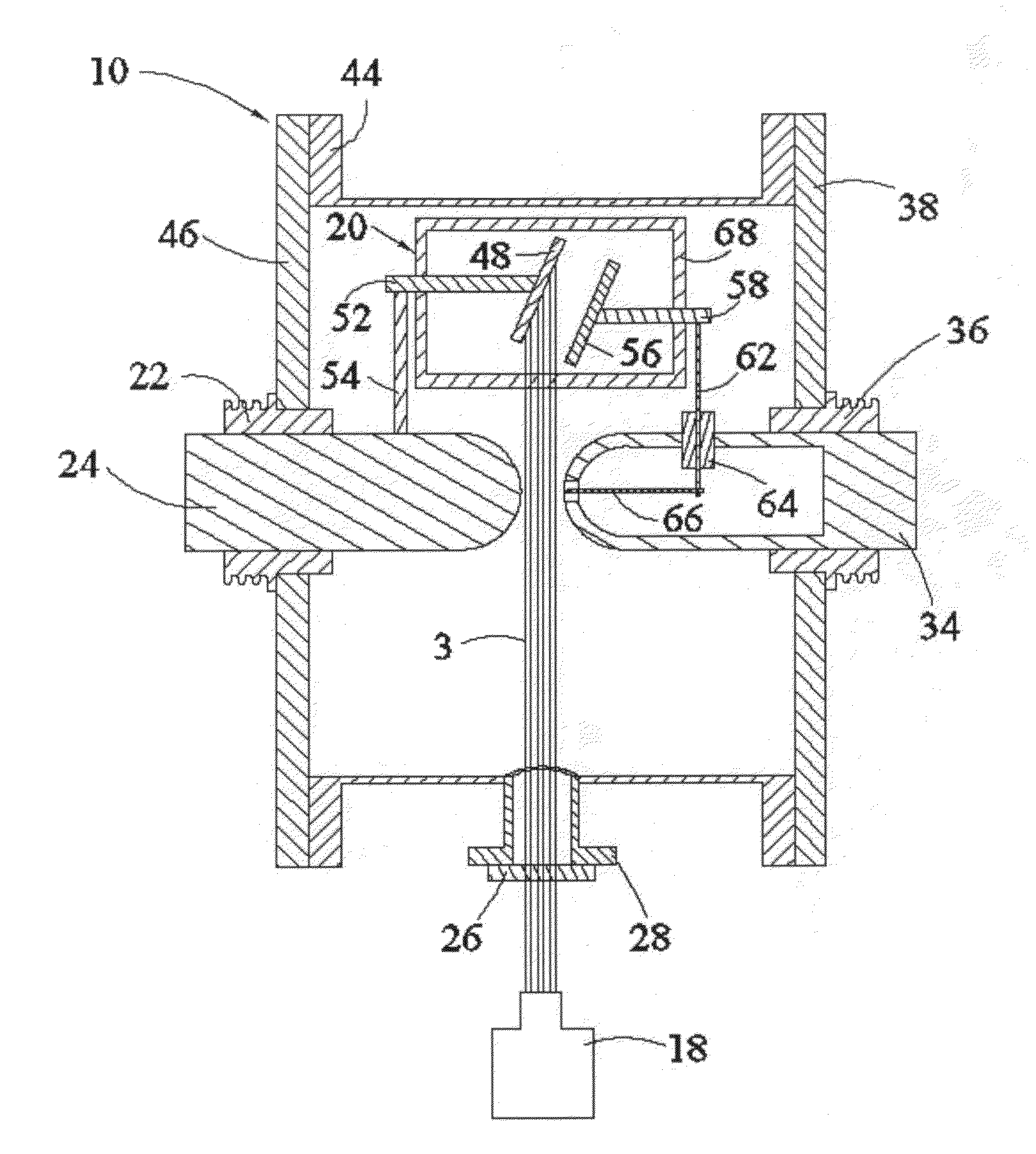
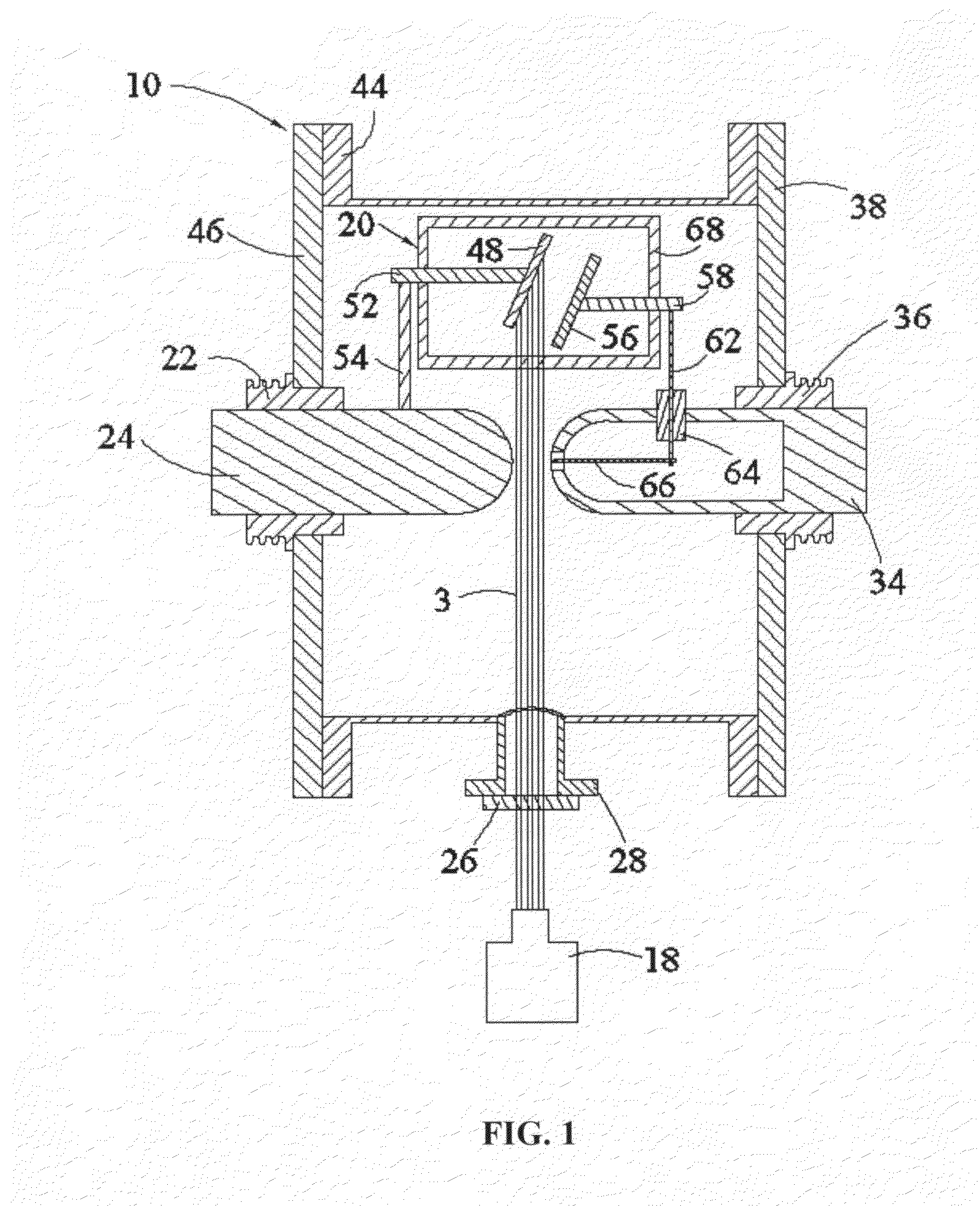
[0022]Referring to FIG. 1, the first embodiment of the switch of the present invention is illustrated. It comprises an UV laser coupled with optical system 18 and a gas-tight housing 10.

[0023]The UV laser system need have a short pulse width, e.g. on the order of hundreds of picoseconds or shorter. Under this circumstance, all of its pulse optical energy can be output in a very short time. Such an UV laser system can be found from common commercial products, too. Numeral 3 in FIG. 1 indicates the laser beam emitted from the UV laser system 18.

[0024]The sealed housing 10 consists of a sidewall 44, end cover 38 and end cover 46. It is full of high voltage isolating mediums such as gases, water or even low vacuum. Cylindrical main electrodes 24 and 34 are welded with high voltage ceramic insulators 22 and 36 individually, while the high voltage insulators 22 and 36 are secured on the end covers 46 and 38, respectively. The main electrodes 24 and 34 are made of a highly conductive and d...


PUM


Abstract

A spark gap switch for controlling the output of a high voltage pulse from a high voltage source, for example, a capacitor bank or a pulse forming network, to an external load such as a high gradient electron gun, laser, pulsed power accelerator or wide band radar. The combination of a UV laser and a high vacuum quartz cell, in which a photocathode and an anode are installed, is utilized as triggering devices to switch the spark gap from a non-conducting state to a conducting state with low delay and low jitter.

Description

GOVERNMENT RIGHTS[0001]This invention was made with government support under Grant No. DE-FG03-02ER83402 awarded by the U.S. Energy Department. The government may have certain rights in the invention.BACKGROUND OF THE INVENTION[0002]1. Field of the Invention[0003]The present invention provides a high voltage spark gap switch controlled by a laser-photocathode subsystem. A double-triggering mechanism is used for reliably closing the spark gap switch while keeping the low jitter properties of the laser triggering.[0004]2. Description of Prior Art[0005]High voltage switch is one of the elementary devices employed in pulsed power techniques. Ideally, it controls the flow of current in a circuit in two states: either the current flows at a value determined by the other components in series with it, or the current does not flow at all. There are many considerations when choosing a switch; for example, large current and / or voltage handling capacity, compact size, price, durability and reli...

Claims


Application Information

Patent Timeline
Patent Type & Authority Applications(United States)
IPC IPC(8): H01J21/00H01J5/16H01J1/34
CPCH01J1/34H01J21/00H01J5/16H01T2/00H01T2/02H01T1/20
Inventor CHEN, PINGLUNDQUIST, MARTIN L.YU, DAVID U.L.
Owner DULY RES
Why Eureka
Try Eureka