Emulsion chemistry for encapsulated droplets

a technology of encapsulated droplets and emulsion chemistry, which is applied in the field of encapsulated droplets emulsion chemistry, can solve the problems of less accurate assays, increased cost, and more complex instrumentation

Active Publication Date: 2011-09-08
BIO RAD LAB INC
View PDF102 Cites 137 Cited by
  • Summary
  • Abstract
  • Description
  • Claims
  • Application Information

AI Technical Summary

Benefits of technology

[0011]The present disclosure provides a system, including methods, apparatus, compositions, and kits, for making and using a stabilized emulsion. A method of generating a stabilized emulsion is provided. In the method, an aqueous phase may be provided. The aqueous phase may include an effective concentration of one or more skin-forming pr

Problems solved by technology

However, mixing smaller volumes can require more complex instrumentation, which increases cost.
Also, assays performed in smaller volumes may tend be less accurate.
However, maintaining the integrity of droplets can present a challenge.
For example, emulsions can become unstable as the packing density of droplets is increased, because droplet proximity enables coalescence.
This instability limits the ability to store droplets.
Also, the tendency of droplets to coalesce at a h

Method used


Image

  • Emulsion chemistry for encapsulated droplets
  • Emulsion chemistry for encapsulated droplets
  • Emulsion chemistry for encapsulated droplets

Examples


example 1

Selective Removal of Continuous Phase from an Emulsion

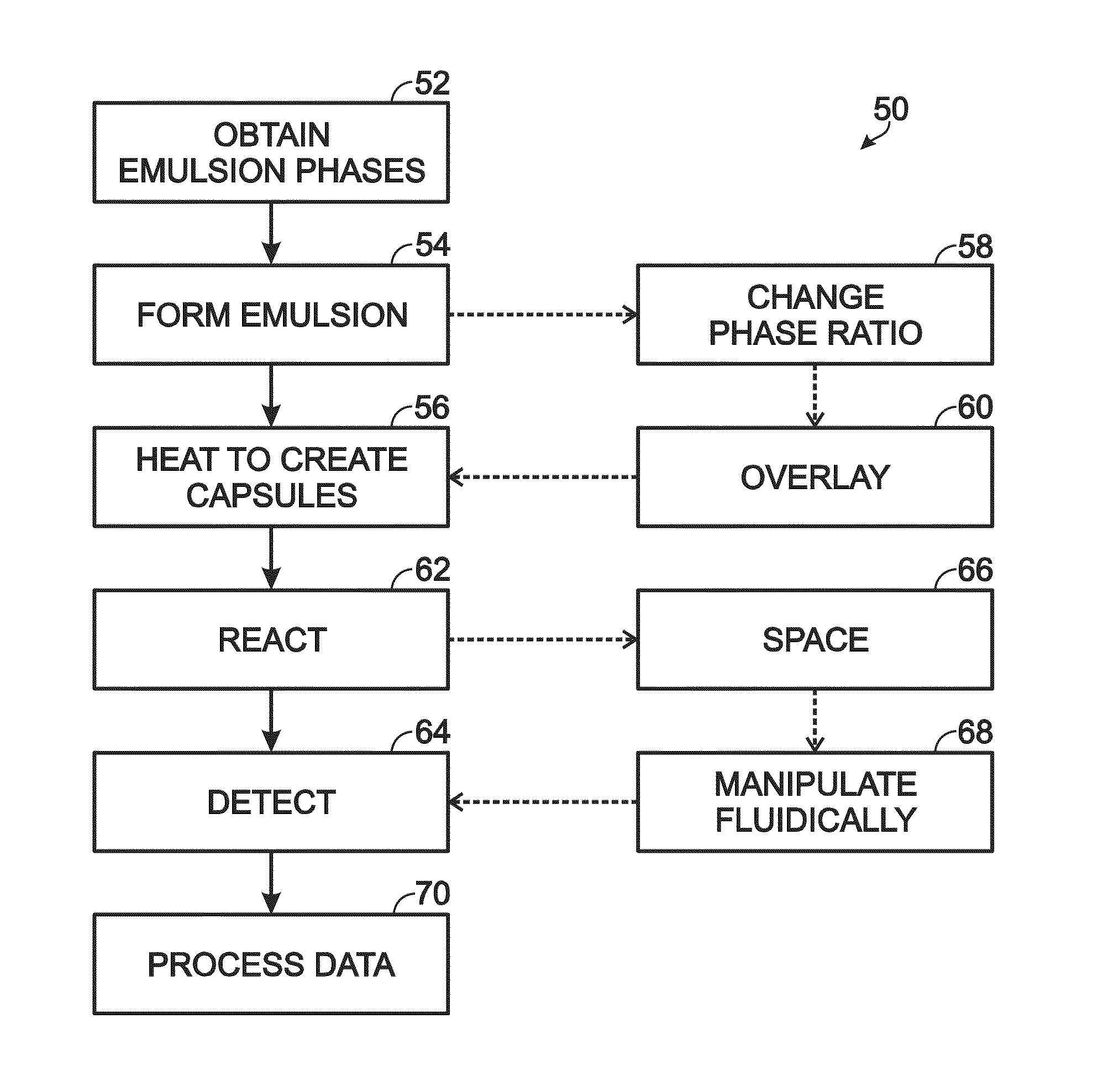
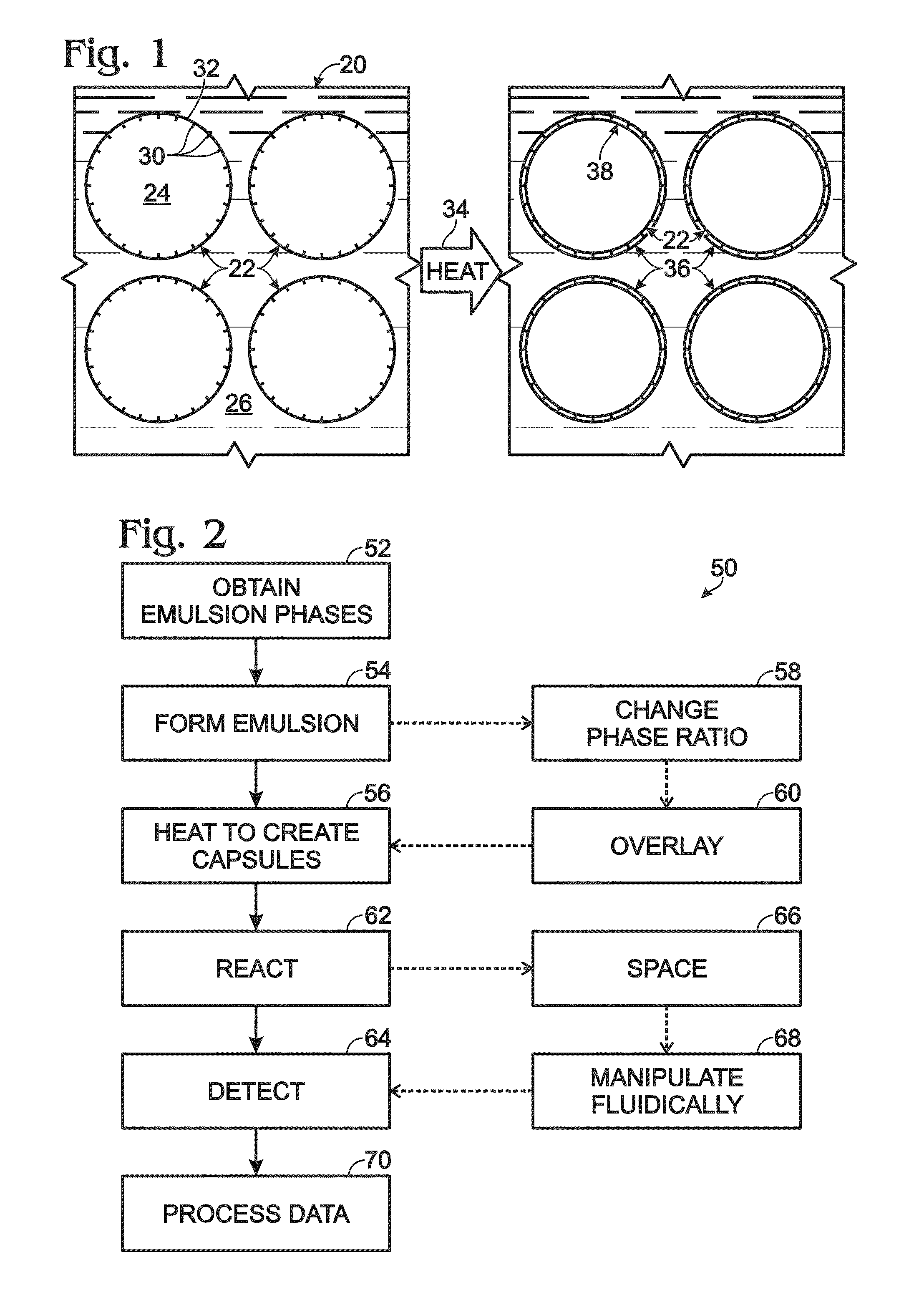
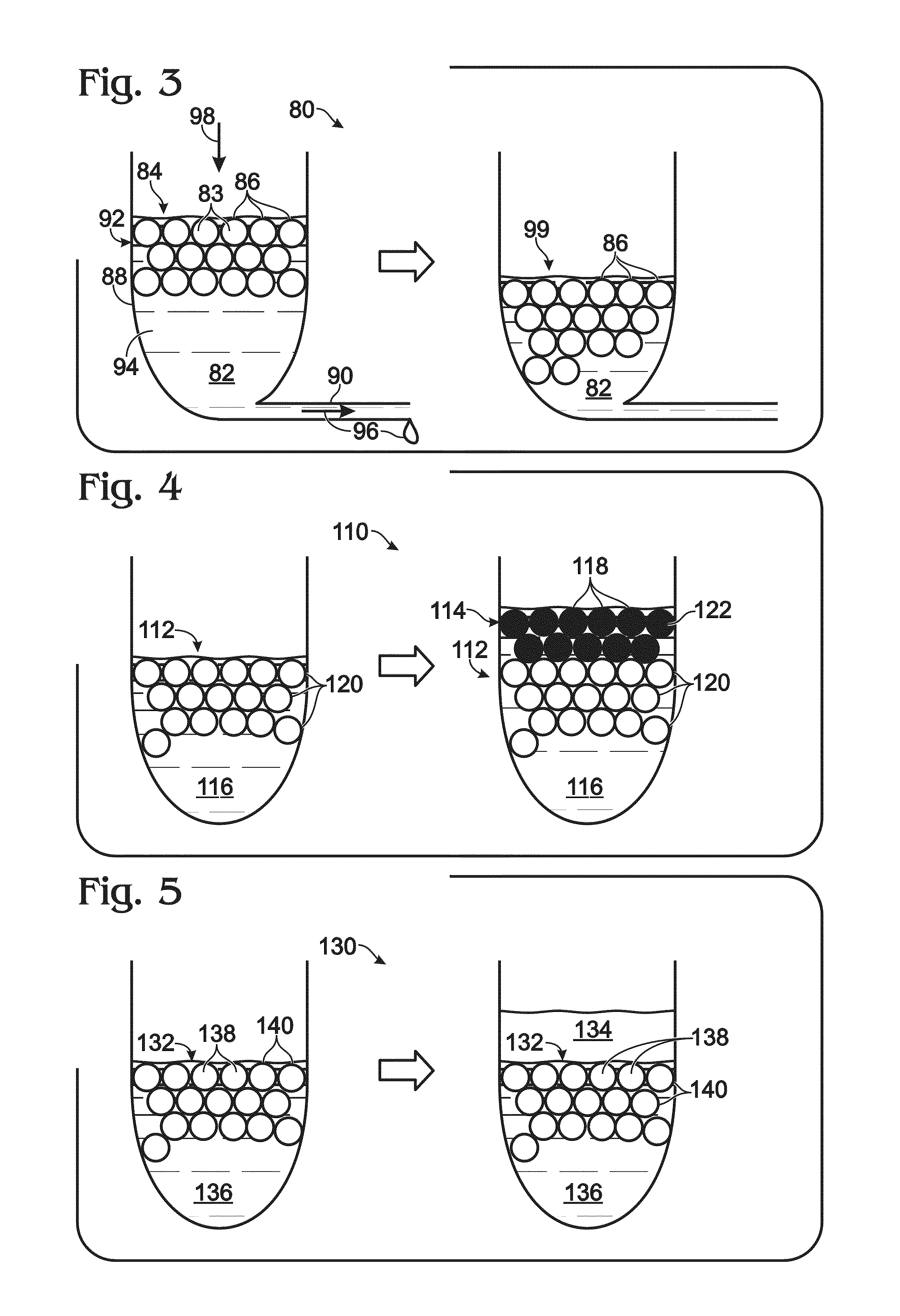
[0166]This example describes an exemplary approach 80 to removing a continuous phase 82 selectively (relative to a dispersed phase 83) from an emulsion 84, to increase the volume fraction occupied by droplets (or capsules) 86; see FIG. 3. Emulsion 84 may be held by a reservoir 88 having a port 90. The port may be formed near or at the bottom of the reservoir, if droplets 86 are buoyant in the continuous phase (as shown here), or may be formed at a higher position of the reservoir if the droplets sink in the continuous phase.

[0167]Buoyant droplets may move within the continuous phase over time toward the top of the emulsion, in a process termed creaming, if the droplets initially have a more uniform distribution in the entire volume of the continuous phase. As a result, the droplets accumulate over time in an upper region of the continuous phase, to form a droplet layer 92 of aggregated droplets that grows downward as buoyant drop...

example 2

Overlaying an Emulsion

[0168]This example describes exemplary approaches to overlaying an emulsion with liquid; see FIGS. 4 and 5. The use of an overlay may be suited for use with an emulsion having buoyant droplets. In this case, buoyancy causes droplets to collect near the interface of the emulsion with air, which renders the droplets less protected by the continuous phase and more vulnerable to evaporative loss. Also, the presence of an air interface may render the emulsion more susceptible to heat-induced damage to droplets (e.g., droplet breakage).

[0169]FIG. 4 illustrates an approach 110 to overlaying an emulsion 112 by using an overlay emulsion 114. The overlay emulsion may or may not have substantially the same continuous phase 116 as underlying or primary emulsion 112, but generally has a continuous phase that is miscible with the continuous phase of the primary emulsion. The overlay emulsion may include aqueous overlay droplets 118 that are distinguishable from droplets 120 ...

example 3

Spacing Fluids and Capsule Damage

[0175]This example describes exemplary spacing fluids with distinct effects on capsule shape and integrity, and presents micrographs showing these effects; see FIGS. 6A, 6B, and 7A-D.

[0176]FIGS. 6A and 6B show a pair of micrographs of capsules from emulsions that have been exposed to a spacing fluid composed of a base oil without surfactant (FIG. 6A) or with surfactant (FIG. 6B). Droplets were generated in HFE 7500 fluorinated oil with 1.8% w / w of Krytox-AS as surfactant. Excess continuous phase was removed, and then the droplets were heated to form capsules. A spacing fluid was added to the continuous phase, which substantially increased the volume fraction of the continuous phase in the emulsion. The spacing fluid was either base oil (HFE 7500) without surfactant (FIG. 6A) or with surfactant at the same concentration as for droplet generation (1.8% w / w of Krytox-AS). In other words, the spacing fluid had the same composition as the original continu...


PUM

PropertyMeasurementUnit
Temperatureaaaaaaaaaa

Abstract

System, including methods, apparatus, compositions, and kits, for making and using a stabilized emulsion. A method of generating a stabilized emulsion is provided. In the method, an aqueous phase may be provided. The aqueous phase may include an effective concentration of one or more skin-forming proteins. An emulsion may be formed. The emulsion may include droplets of a dispersed phase disposed in a continuous phase, with the aqueous phase being the continuous phase or the dispersed phase. The emulsion may be heated to create an interfacial skin between each droplet and the continuous phase, to transform the droplets into capsules.

Description

CROSS-REFERENCES TO PRIORITY APPLICATIONS[0001]This application is based upon and claims the benefit under 35 U.S.C. §119(e) of U.S. Provisional Patent Application Ser. No. 61 / 309,845, filed Mar. 2, 2010; U.S. Provisional Patent Application Ser. No. 61 / 341,218, filed Mar. 25, 2010; U.S. Provisional Patent Application Ser. No. 61 / 317,635, filed Mar. 25, 2010; U.S. Provisional Patent Application Ser. No. 61 / 380,981, filed Sep. 8, 2010; U.S. Provisional Patent Application Ser. No. 61 / 409,106, filed Nov. 1, 2010; U.S. Provisional Patent Application Ser. No. 61 / 409,473, filed Nov. 2, 2010; U.S. Provisional Patent Application Ser. No. 61 / 410,769, filed Nov. 5, 2010; and U.S. Provisional Patent Application Ser. No. 61 / 417,241, filed Nov. 25, 2010; each of which is incorporated herein by reference in its entirety for all purposes.CROSS-REFERENCES TO ADDITIONAL MATERIALS[0002]This application incorporates by reference in their entirety for all purposes the following materials: U.S. Pat. No. ...

Claims


Application Information

Patent Timeline
IPC IPC(8): C12P19/34C12Q1/68
CPCC12Q1/6846C12Q1/6848C12Q2527/125C12Q2563/159C12Q1/6816C12Q1/686
Inventor HIDDESSEN, AMY L.HINDSON, BENJAMIN J.
Owner BIO RAD LAB INC
Why Eureka
Try Eureka