Micromechanical component and method for its production

a micromechanical and component technology, applied in the field of micromechanical components, can solve the problems of large surface requirements of components, large number of process steps, and complex methods, and achieve the effect of small size, simple and cost-effectiv

Inactive Publication Date: 2011-09-15
ROBERT BOSCH GMBH
View PDF4 Cites 23 Cited by
  • Summary
  • Abstract
  • Description
  • Claims
  • Application Information

AI Technical Summary

Benefits of technology

[0013]A micromechanical component is also proposed, according to the present invention. The component has a first substrate and a second substrate connected to the first substrate. The first substrate has a micropattern having a movable functional element. The first and the second substrate are connected to each other in such a way that the functional element is enclosed by a closed cavity. The ...

Problems solved by technology

The development of the buried printed circuit traces, which lead to contact elements next to the MEMS structure and outside the cap, results in a large surface requirement of the component.
Furthermore, the method is complex, and requires a large number of process steps.
For example, the method may bring along with it the use of more than ten lithographic patterning planes and lithog...

Method used


Image

  • Micromechanical component and method for its production
  • Micromechanical component and method for its production
  • Micromechanical component and method for its production

Examples


Embodiment Construction

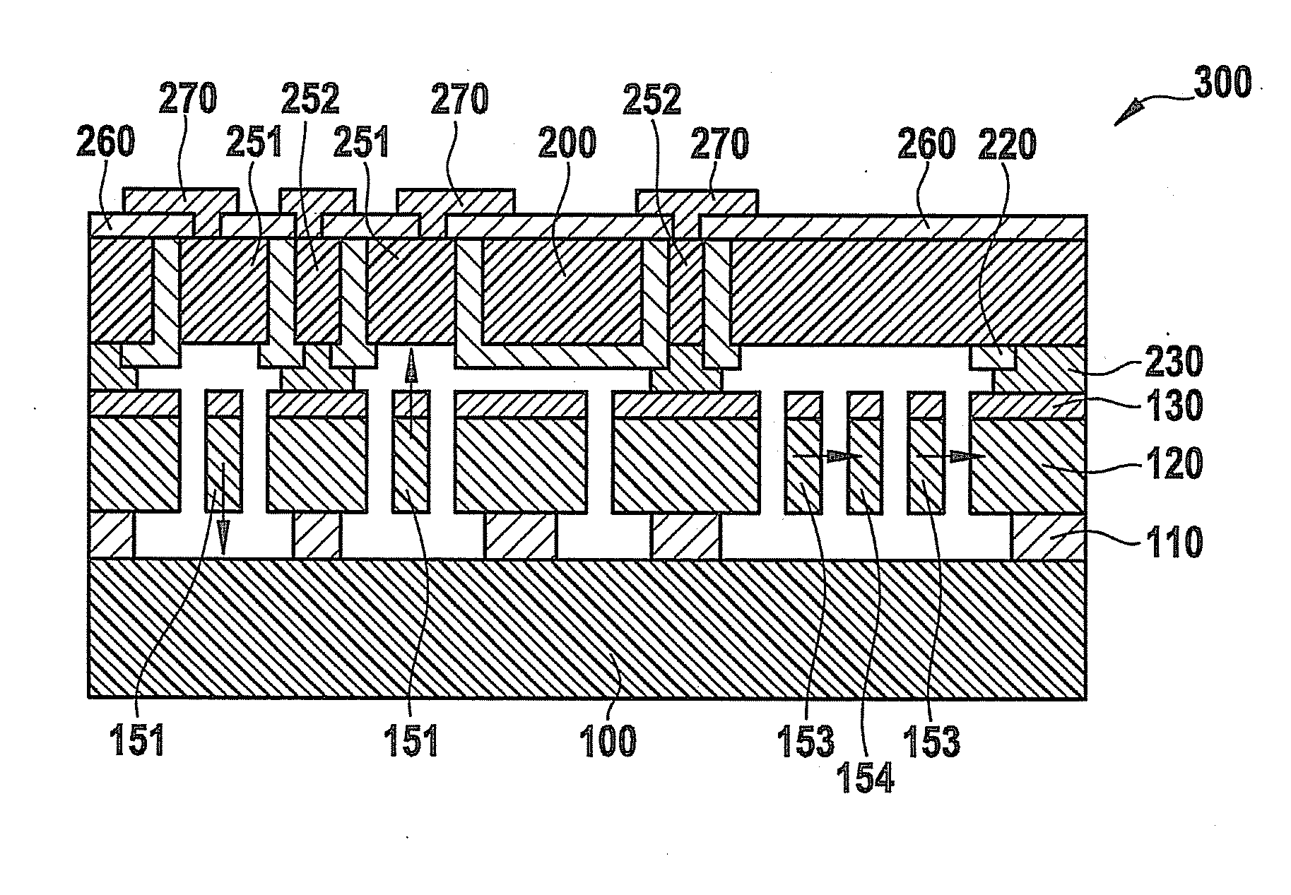
[0022]The following FIGS. 1 through 7 schematically show the production of a micromechanical component 300 which, for example, may be used as an inertial sensor in a motor vehicle. The usual processes and materials that are customary in semiconductor technology may be used in the production.

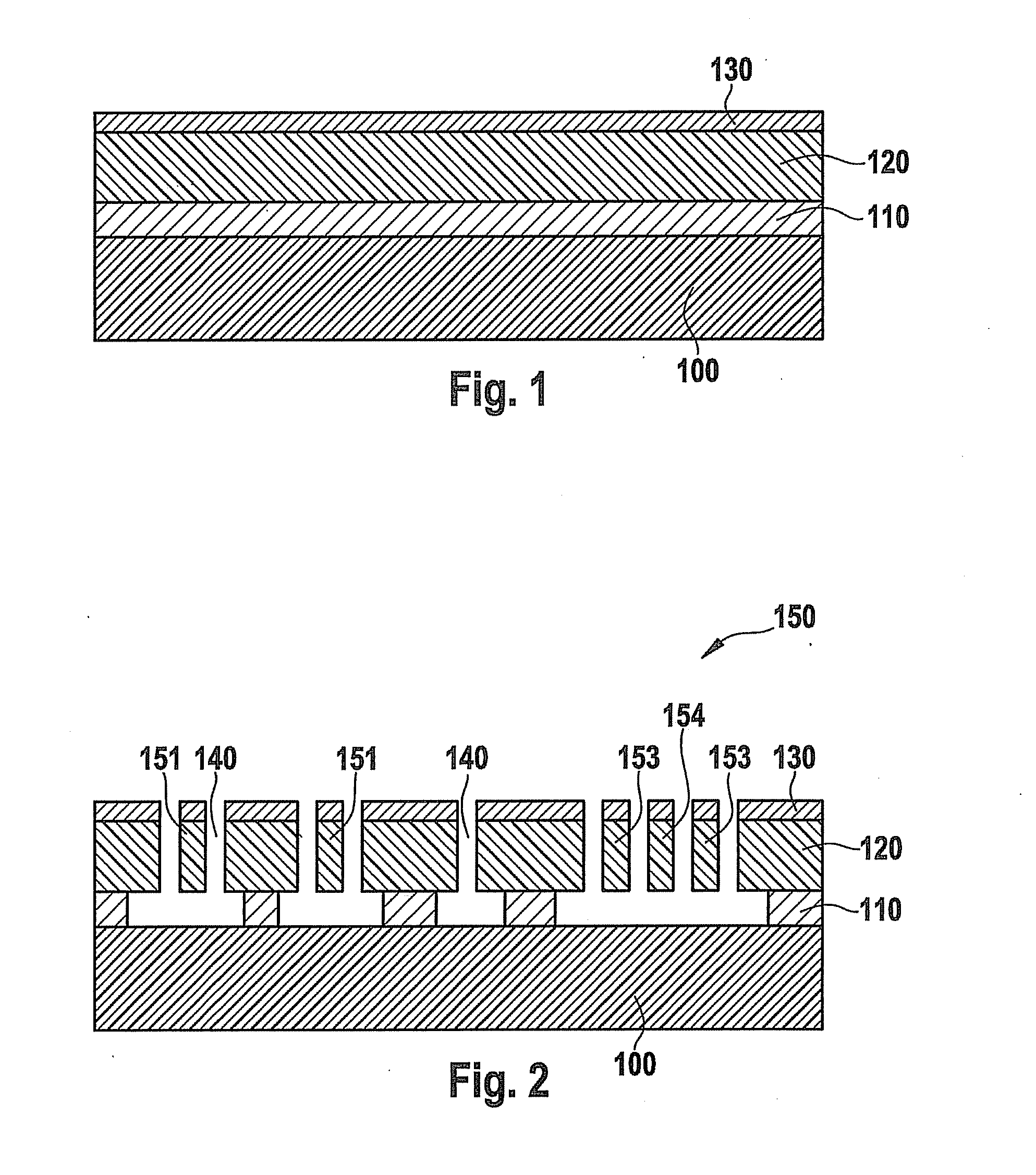
[0023]FIGS. 1 and 2 show the production of a functional substrate 100 having a micromechanical or MEMS structure 150 for component 300. At the beginning, a substrate 100 is provided, which has a semiconductor material such as silicon, for example. Substrate 100 may be a customary wafer having a diameter of 8 inches (20.0 mm).

[0024]Subsequently, as shown in FIG. 1, a sacrificial layer 110 is applied onto substrate 100 and a functional layer 120 is applied onto sacrificial layer 110. Sacrificial layer 110 may have silicon oxide. Functional layer 120 may be a so-called epi-polysilicon layer, that is, a polycrystalline silicon layer produced in an epitaxy method. Functional layer 120 may optionally b...


PUM

PropertyMeasurementUnit
Areaaaaaaaaaaa
Metallic bondaaaaaaaaaa

Abstract

A method for producing a micromechanical component, includes providing a first substrate, developing a micropattern on the first substrate, the micropattern having a movable functional element, providing a second substrate, and developing an electrode in the second substrate for the capacitive recording of a deflection of the functional element. The method further includes connecting the first and the second substrate, a closed cavity being formed which encloses the functional element, and the electrode bordering on the cavity in an area of the functional element.

Description

FIELD OF THE INVENTION[0001]The present invention relates to a micromechanical component having a first substrate and a second substrate that is connected to the first substrate, the first substrate having a micropattern having a movable functional element, and the first and the second substrate being connected to each other in such a way that the functional element is enclosed by a cavity. Furthermore, the present invention relates to a method for manufacturing such a component.BACKGROUND INFORMATION[0002]Micromechanical components, which are used, in the automotive field, as inertial and acceleration sensors, for example, normally have a micropattern having a movable functional element. The micropattern is also designated as a MEMS structure (microelectromechanical system). During the operation of the sensors, the deflection of a functional element is detected, for instance, by a change in the electrical capacity compared to a fixed reference electrode.[0003]A common method for pr...

Claims


Application Information

Patent Timeline
IPC IPC(8): G01R27/26H05K3/36
CPCB81B7/007B81B2201/033Y10T29/49126B81C2203/0118B81C2203/036B81B2207/095
Inventor FEYH, ANDO
Owner ROBERT BOSCH GMBH
Why Eureka
Try Eureka