Assembly method for a tiled radiation detector

Inactive Publication Date: 2011-09-15
TRIXELL S
View PDF2 Cites 12 Cited by
  • Summary
  • Abstract
  • Description
  • Claims
  • Application Information

AI Technical Summary

Benefits of technology

[0037]An optically clear film adhesive is applied on the scintillator panel before the said alignment takes place. In one aspect of the embodiment, vacuum and clean-room conditions are used at least during application of the adhesive to prevent entrapment of air bubbles or particles between adhesive film and scintillator panel.
[0038]According to another embodiment of the invention, a method of making a tiled detector comprises the following step: aligning detector tiles one after another with their active (front) side down on to an alignment fixture to form an array of detector tiles; than temporally attaching a mechanical fixture to the bac

Problems solved by technology

For example, x-ray, computed tomography, positron emission tomography, nuclear, and gamma ray imaging detectors often use an ionizing photon detector material, such as Cadmium Zinc Telluride (CZT), Cadmium Telluride (CdTe), and various other crystalline semiconductor materials, which have size limitations due to a variety of production factors.
For example, imaging detectors using the CZT material generally require multiple tiles, because CZT crystals can only be grown in relatively small sizes due to yield problems with current technology.
Unfortunately, the tiling process tends to create gaps that create visible ar

Method used


Image

  • Assembly method for a tiled radiation detector
  • Assembly method for a tiled radiation detector
  • Assembly method for a tiled radiation detector

Examples


Embodiment Construction

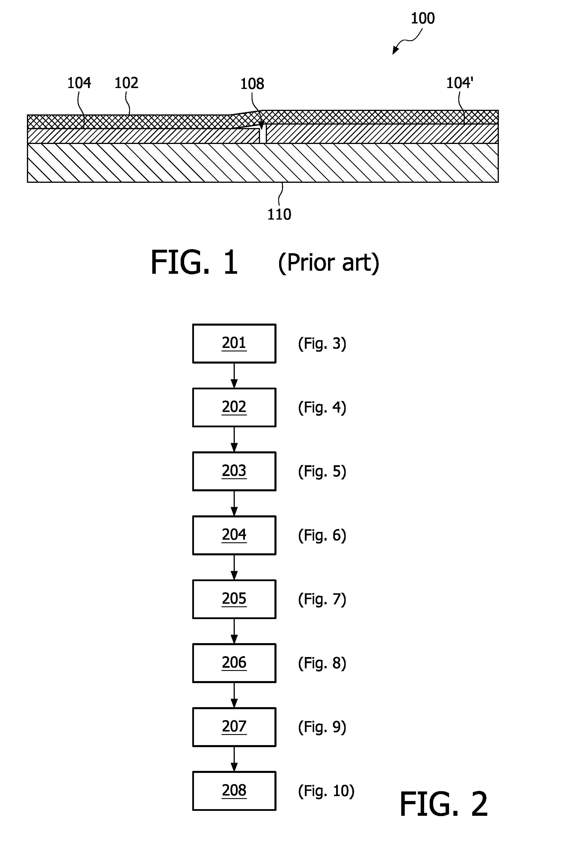
[0066]According to FIG. 1, a flat tiled detector assembly 100 based on indirect conversion is shown, wherein a scintillator 102 is coupled to a readout panel composed of one or more detector tiles 104, 104′ arranged on to a substrate layer 110. The scintillator 102 can be either directly deposited onto the readout panel or first deposited onto a substrate (not shown here) which is then coupled to the readout panel, e.g. with an optical glue or gel. The optical and mechanical properties of this coupling layer have a big impact on image quality (IQ). Hence, misalignment in all three directions x, y, z among detector tiles 104 in a tiled detector assembly 100 results in image artifacts. Z-misalignment results in altimetry differences between detector tiles. This may introduce voids 108 or air bubbles in the coupling layer where the detector tiles 104, 104′ join. Such imperfections affect the local pixel sensitivities of each detector tile, thus leading to image artifacts.

[0067]Accordin...


PUM

PropertyMeasurementUnit
Lengthaaaaaaaaaa
Lengthaaaaaaaaaa
Widthaaaaaaaaaa

Abstract

A tiled detector assembly (1000) and a method for making a tiled radiation detector (1000) is described. The innovative feature of this method is that the xyz misalignment of the detector tiles (304, 304′), the origin of various image artifacts, can be significantly reduced by accurate sizing and alignment of the detector tiles (304, 304′). Consequently, image quality, yield and reliability of as-produced tiled radiation detectors are considerably improved.

Description

FIELD OF THE INVENTION[0001]The present invention relates generally to imaging systems, such as radiographic or X-ray systems, and more particularly, to multi-tile detector assemblies used in such systems and a method of making such assemblies. Even more particularly, the present invention relates to a system and method for assembling detector tiles in manner that minimizes or prevents visible artifacts associated with the tiling.BACKGROUND OF THE INVENTION[0002]Medical diagnostic and imaging systems are ubiquitous in modern health care facilities. Currently, a number of modalities exist for medical diagnostic and imaging systems. These include computed tomography (CT) systems, x-ray systems (including both conventional and digital / digitized imaging systems), magnetic resonance (MR) systems, positron emission tomography (PET) systems ultrasound systems, nuclear medicine systems and so forth.[0003]Medical imaging systems often generate images by radiating a non-intrusive source into ...

Claims


Application Information

Patent Timeline
IPC IPC(8): G01N23/04G01T1/20H05K13/00
CPCY10T29/49004G01T1/00G01T1/2018G01T1/2006
Inventor JORRITSMA, JORRITPOORTER, TIEMENLIJTEN, GERARDUS FRANCISCUS CORNELIS MARIAVAN ROOSMALEN, JOHANNES H.M.SENS, MARTINUS MARIAGROB, TIMON RUTGERTER LAAK, MICHAEL JOHAN FERDINAND MARIE
Owner TRIXELL S
Why Eureka
Try Eureka