Electromedical implant and monitoring system including the electromedical implant

a monitoring system and electromedical technology, applied in the field of electromedical implants, can solve the problems of inability to provide therapy options for patients without monitoring implants, disadvantages and at times cumbersome, and cardiac invasive systems are generally not suitable for patients without cardiac invasive systems, etc., to achieve low blood flow of coronary arteries, reduce vascular elasticity, and reduce pulse transit

Active Publication Date: 2011-09-15
BIOTRONIK SE & CO KG
View PDF11 Cites 1 Cited by
  • Summary
  • Abstract
  • Description
  • Claims
  • Application Information

AI Technical Summary

Benefits of technology

The invention involves an electromedical implant, particularly a pure monitoring implant, for monitoring a cardiac blood flow and an epithoracic peripheral blood flow of a living being, by which a measurement signal associated with the epithoracic peripheral blood flow can be determined in a comparatively simple and yet reliable manner. The invention also involves a monitoring system utilizing the electromedical implant, by which the pulse transit time, and preferably additional patient values derived from the pulse transit time, can be monitored and retrieved either briefly or over an extended period.
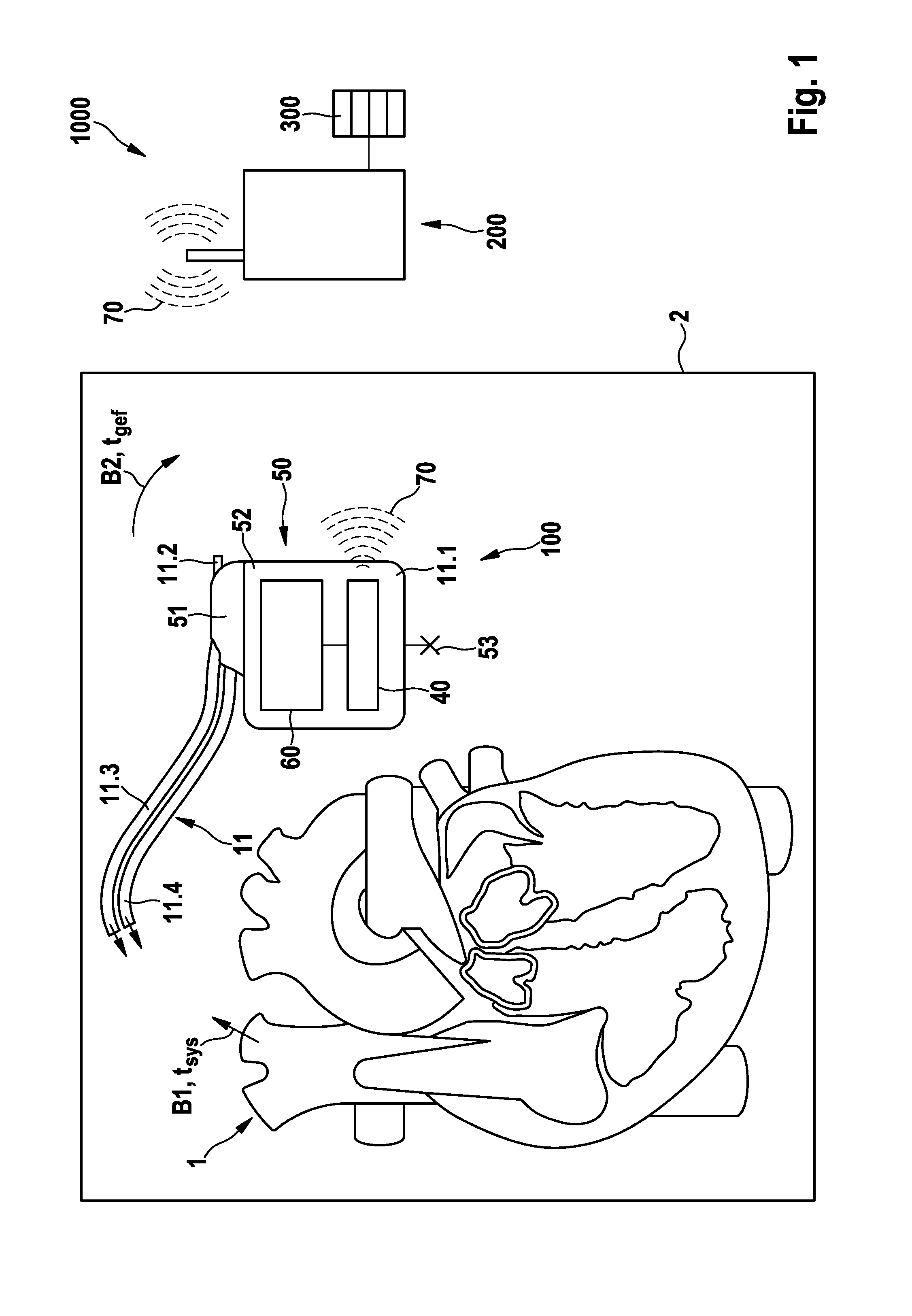
In a particularly preferred version, the electromedical implant is implemented purely as a monitoring implant (i.e., without a therapy option). The monitoring implant can advantageously be implanted subcutaneously or submuscularly and does not require intracardiac electrodes for monitoring the pulse transit time (though use of such electrodes is possible). The electromedical implant allows capture of a measurement signal associated with the cardiac blood flow, and of a measurement signal associated with the epithoracic, peripheral blood flow, in a particularly simple and reliable manner. The implant is compact and easy to implement.
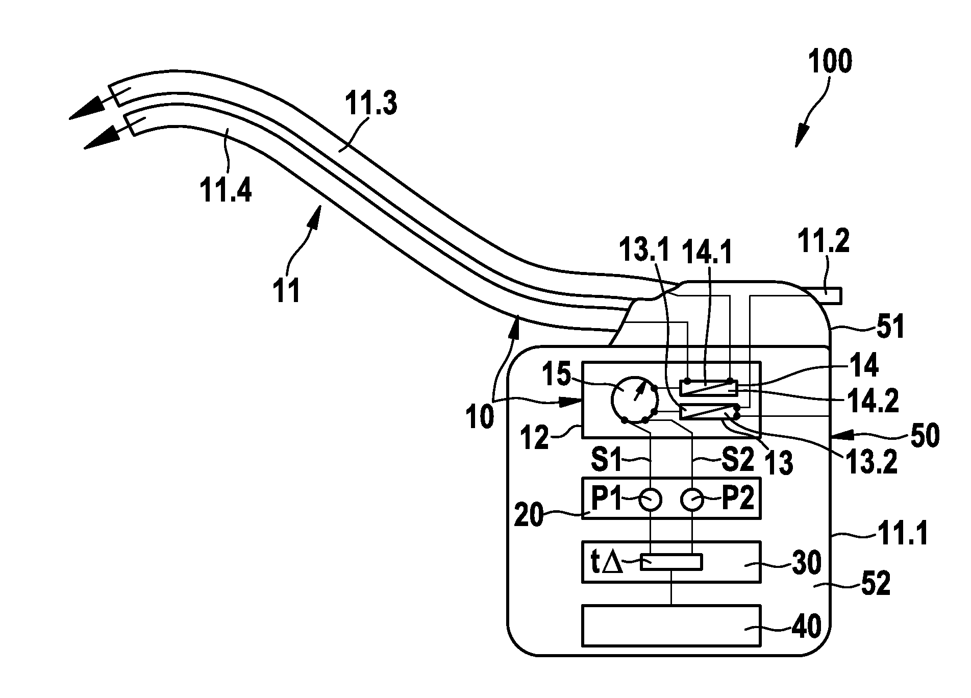
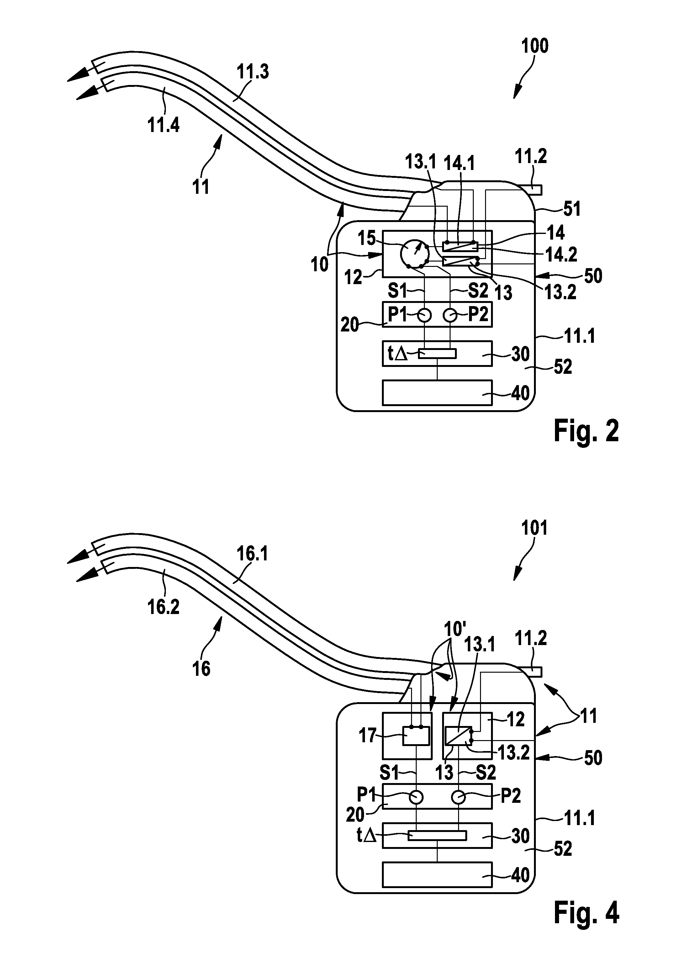
The impedance measuring unit, the monitoring assembly, and the evaluation unit may be provided as part of an electronic circuit provided in a housing of the implant, and which (at least for picking up the second measurement signal) is electrically connected to the electrode assembly. The electrode assembly can advantageously be attached to the housing either directly or by way of a header. The housing preferably includes a battery. In a particularly preferred version, the implant includes a communication module for the wireless transmission of the pulse transit time and / or an evaluation result produced by the evaluation unit on the basis of the pulse transit time. The communication module can preferably be provided in the housing as a telemetry module. A telemetric connection of the electromedical implant to the monitoring system via the communication module enables automatic remote monitoring of a patient by way of the electromedical implant. The patient can thus be monitored remotely by the physician or a service center, and alarm conditions can be generated based on the transmitted pulse transit time and / or evaluation signals, which are displayed in the service center and / or directly at the physician's practice. In this way, a physician can be notified of critical conditions of a patient via the service center, either directly or by way of further communication means, such as an Internet platform, SMS, e-mail, fax or the like. A monitoring system can make patient conditions reported by the electromedical implant available for visualization.
A reduced pulse transit time, for example, can indicate reduced vascular elasticity. Associated therewith is low blood flow of the coronary vessels and an increased risk of cardiac infarction. Low vascular elasticity promotes the deterioration of health in the case of chronic cardiac insufficiency. Vascular elasticity also influences the treatment possibilities for hypertension. Knowledge of the vascular elasticity and the changes thereof can optimize the type and dosage of drugs.
The evaluation result preferably includes a parameter indicative of the blood vessel state and / or a parameter indicative of the blood pressure, which can be determined from the pulse transit time. In addition, the evaluation result may include additional parameters which are indicative of a condition of the living being (patient) and which, in principle, can be determined on the basis of the pulse transit time using suitable means and algorithms. The pulse transit time and / or the evaluation results are made available for further use by the memory unit, which can be provided in the implant or the receiving unit. In this way, the pulse transit time and / or the evaluation results can be saved in the form of trends and statistics, such as histograms, and can be queried by the physician during a follow-up examination using a suitable interrogation device. However, a query can also be conducted directly by the patient, or by an authorized service center.
The detector unit preferably implements the aforementioned arrangements using a frequency module and / or a detector. In a particularly preferred version, the frequency module determines a background signal in the form of a high-frequency impedance measurement signal, in particular at a frequency above the first and / or second excitation frequencies mentioned above. Changing the frequency for an impedance measurement has been found to result in a changed contrast between the blood and tissue (skin and muscles). It was found that blood has higher conductivity than tissue, and that this discrepancy decreases as the frequency increases, and thus a higher contrast exists between blood and tissue at lower frequencies than at high frequencies. As a result, higher frequencies tend to be more greatly influenced by geometric changes, and the differences between lower and higher frequency measurements can be used to isolate and suppress geometric changes in the first and / or second measurement signals.

Problems solved by technology

Contrary to therapy implants, such as implantable cardiac stimulators or the like, an monitoring implant for monitoring blood flows of a living being (patient) provides no therapy options.
While such non-invasive systems have proven useful for monitoring purposes, they are disadvantageous and at times cumbersome.
However, cardiac invasive systems are generally not a suitable option for patients having no therapy indication, i.e., no (presently) defined need for therapy.
The implantation of probes in the heart, for example for determining an ECG signal using a cardiac stimulator, is complex and associated with risks for the patient.
However, this is unsuitable for patients without an electrotherapy indication.

Method used


Image

  • Electromedical implant and monitoring system including the electromedical implant
  • Electromedical implant and monitoring system including the electromedical implant
  • Electromedical implant and monitoring system including the electromedical implant

Examples


Embodiment Construction

FIG. 1 schematically illustrates an exemplary preferred version of a monitoring system 1000 including an electromedical implant 100, which is equipped to monitor a cardiac blood flow B1 (conceptually illustrated by an arrow), and an epithoracic peripheral blood flow B2 of a living being (also conceptually illustrated by an arrow), the living being preferably being a patient who may or may not have a diagnosis of cardiac insufficiency. Also conceptually illustrated are the heart 1 and the thorax 2 of the patient (the thorax being represented by the box 2 about the heart 1 and the implant 100), with the blood flows B1 and B2 being shown within the thorax 2. The implant 100 is preferably designed purely as a monitoring implant, in other words, it does not perform therapy. The implant 100 includes a housing 50 having a housing container 52, a header 51, and an electrode assembly 11 connected to the housing 50. The implant 100 is situated in the thorax 2 of the patient, subcutaneously in...


PUM


Abstract

An electromedical implant (100, 101, 102, 103) for monitoring a cardiac blood flow (B1) of a patient includes a detector (10, 10′, 10″) which obtains a first measurement signal (S1) associated with the cardiac blood flow (B1) and a second measurement signal (S2) associated with the epithoracic, peripheral blood flow (B2). A monitoring assembly (20) then generates a first parameter (P1) from the first measurement signal (S1) which is indicative of a time (tsys) at which blood is ejected from the heart, and a second parameter (2) from the second measurement signal (S2) which is indicative of a time (tgef) of a blood pulse in the thoracic tissue which is associated with the ejection of blood. An evaluation unit (30) then generates a pulse transit time (Δt=tgef−tsys) from the first parameter (P1) and the second parameter (P2). The detector (10, 10′, 10″) includes an impedance measuring unit (12) having an electrode assembly (11, 11′) for detection of at least the second measurement signal (S2) in the form of an impedance signal.

Description

FIELD OF THE INVENTIONThe invention relates to an electromedical implant for monitoring a cardiac blood flow and an epithoracic, peripheral blood flow of a living being. The invention further relates to a monitoring system including the electromedical implant.BACKGROUND OF THE INVENTIONAn electromedical implant of the type mentioned above can be designed and / or used only for monitoring (in which case it is typically referred to as a monitoring implant), or for both monitoring and therapy (in which case it is typically referred to as a therapy implant). Contrary to therapy implants, such as implantable cardiac stimulators or the like, an monitoring implant for monitoring blood flows of a living being (patient) provides no therapy options. A monitoring implant can be useful for patients having no identified need for therapy in order to monitor the patient's blood flows. For example, the conditions for electrotherapy may not (yet) be diagnosed, or the proper type of electrotherapy to b...

Claims


Application Information

Patent Timeline
Patent Type & Authority Applications(United States)
IPC IPC(8): A61B5/0245
CPCA61B5/029A61B5/0295A61B5/0402A61B5/7275A61B5/6846A61B5/721A61B5/7214A61B5/0535A61B5/318
Inventor CZYGAN, GERALDLIPPERT, MICHAELSKERL, OLAF
Owner BIOTRONIK SE & CO KG
Why Eureka
Try Eureka