Optical device with athermal slots for temperature dependence curvature reduction

Inactive Publication Date: 2011-09-22
BROADEX TECH UK LTD
View PDF34 Cites 23 Cited by
  • Summary
  • Abstract
  • Description
  • Claims
  • Application Information

AI Technical Summary

Benefits of technology

[0013]In one aspect of the invention, roughly stated, Applicants have discovered that a compensation material within slot elongated in a direction parallel to a segment of waveguide in an arrayed waveguide grating apparatus can compensate for both first and second order change in refractive index of the base waveguide material over temperature. Unlike the transverse slots of conventional linear athermalization techniques, the elongated slot generally parallel to the base material defines a composite waveguide section having a second order effective inde

Problems solved by technology

In conventional integrated optical multiplexer and demultiplexer devices, the medium forming the arrayed waveguides has a noticeable temperature dependency which results in changes in the central transmission wavelength which may exceed the transmission bandwidth.
As a result, temperature variations that are within a specified device operating temperature range (e.g. from about 0 C to about 70 C) induce a wavelength shift which is unacceptable in comparison to the typical accuracy requirements.
But the use of heating elements to achieve active athermalization is undesirable because it increases the overall cost, size and complexity of the device, reduces device lifetimes, and consumes considerable power.
Peltier coolers can also be used, but these suffer from many of the same inadequacies.
However, a problem with this arrangement is that as the temperature varies, the difference in refractive index between the core and the cladding varies, and in the worst case, light may not be able to be g

Method used


Image

  • Optical device with athermal slots for temperature dependence curvature reduction
  • Optical device with athermal slots for temperature dependence curvature reduction
  • Optical device with athermal slots for temperature dependence curvature reduction

Examples


Example

[0040]The following description is presented to enable any person skilled in the art to make and use the invention, and is provided in the context of a particular application and its requirements. Various modifications to the disclosed embodiment will be readily apparent to those skilled in the art, and the general principles defined herein may be applied to other embodiments and applications without departing from the spirit and scope of the present invention. Thus, the present invention is not intended to be limited to the embodiments shown, but is to be accorded with the widest scope consistent with the principles and features disclosed herein.

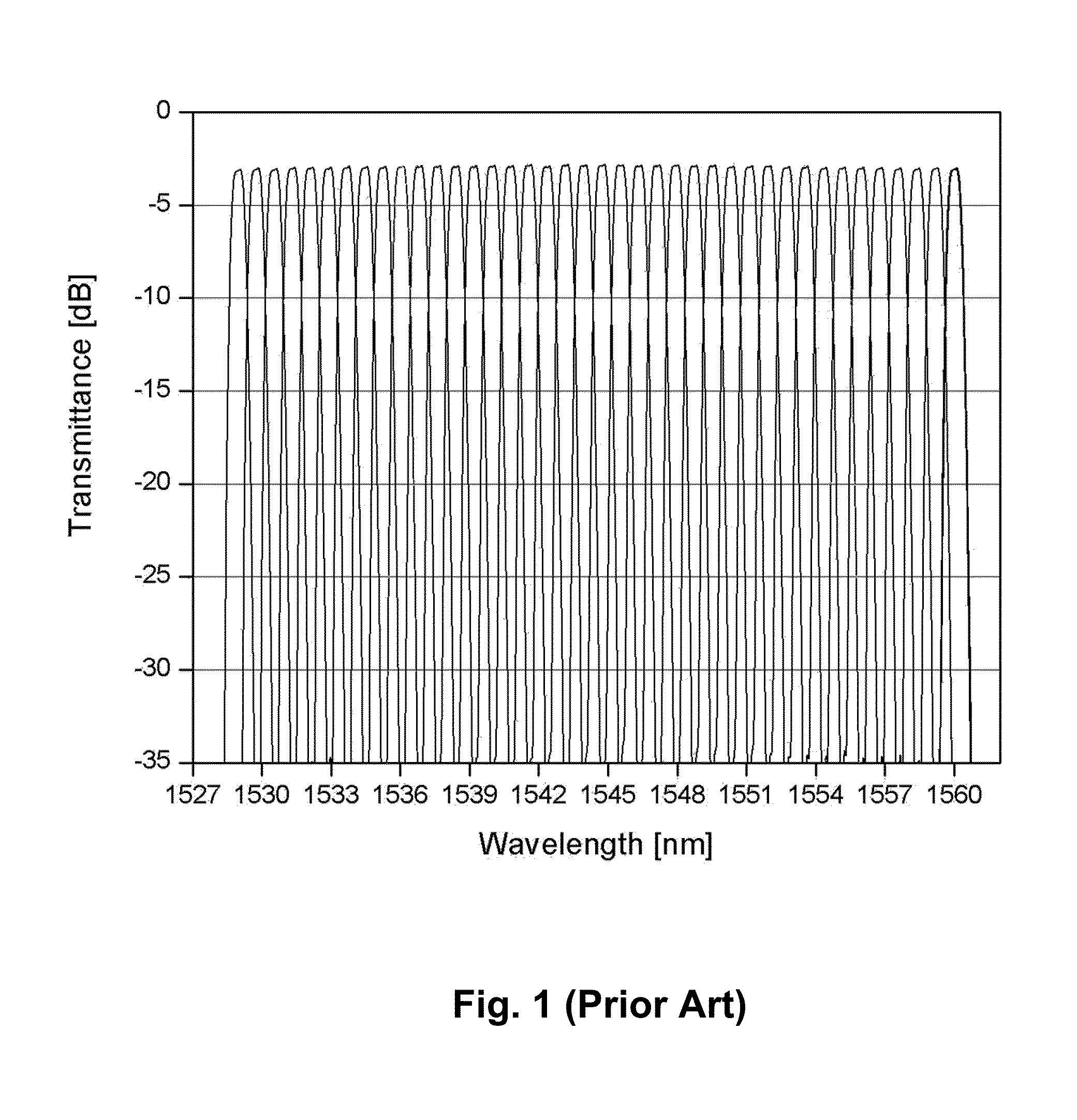
[0041]FIG. 1 illustrates the spectral response of a typical AWG acting as a wavelength division demultiplexer. The plot illustrates the transmittance observed at each of a plurality of different output channels, all superimposed onto a single plot. Alternatively, the plot illustrates the spectral response of a typical AWG acting as a wavele...


PUM


Abstract

In one aspect of the invention, roughly stated, Applicants have discovered that a compensation material within slot elongated in a direction parallel to a segment of waveguide in an arrayed waveguide grating apparatus can compensate for both first and second order change in refractive index of the base waveguide material over temperature. Unlike the transverse slots of conventional linear athermalization techniques, the elongated slot generally parallel to the base material defines a composite waveguide section having a second order effective index of refraction temperature dependency which can be utilized to accurately minimize the temperature dependence of the overall optical path length to both the first and second order. The techniques described herein are also generalizeable to neutralization of the optical path length temperature dependence to any order.

Description

CROSS-REFERENCE TO RELATED APPLICATIONS[0001]This application claims the benefit of U.S. Provisional Application No. 61 / 315,824 entitled “Optical Device with Athermal Slots for Temperature Dependence Curvature Reduction” filed 19 Mar. 2010, which is incorporated by reference herein.BACKGROUND[0002]1. Field of the Invention[0003]The present invention relates generally to optical grating devices, and more particularly to techniques for athermalizing such devices.[0004]2. Description of Related Art[0005]Computer and communication systems place an ever-increasing demand upon communication link bandwidths. It is generally known that optical fibers offer a much higher bandwidth than conventional coaxial links. Further, a single optical channel in a fiber waveguide uses a small fraction of the available bandwidth of the fiber. In wavelength division multiplexed (WDM) optical communication systems, multiple optical wavelength carriers transmit independent communication channels at different...

Claims


Application Information

Patent Timeline
IPC IPC(8): G02B6/34G02B6/10
CPCG02B6/12028G02B6/12011
Inventor BULTHUIS, HINDRIK FREERKMC DADE, PAULABEELEN, GUNTER B.
Owner BROADEX TECH UK LTD
Why Eureka
Try Eureka