Gaseous Ammonia Removal System

a technology of ammonia removal and ammonia gas, which is applied in the preparation of carboxylic compounds, separation processes, organic chemistry, etc., can solve the problems of affecting the health of workers and birds, affecting the conversion of feed and weight gain of birds, and high ammonia levels, so as to reduce the level of nh3

Active Publication Date: 2011-09-22
US SEC AGRI
View PDF1 Cites 8 Cited by
  • Summary
  • Abstract
  • Description
  • Claims
  • Application Information

AI Technical Summary

Benefits of technology

[0014]It is therefore ah object of the present invention to provide a system for at least reducing levels of NH3 in an enclosed area and recovering N in a purified concentrated form.

Problems solved by technology

Volatilization of NH3 inside poultry housing often results in an excessive accumulation of NH3 in the air, which can negatively affect the health of both workers and birds (Kirychuk et al., Journal of Occupational and Environmental Medicine 48 (7):741-748, 2006; Ritz et al., Journal of Applied Poultry Research 13:684-692, 2004; Rylander and Carvalheiro, International Archives of Occupational and Environmental Health 79 (6):487-490) 2006).
Although increased ventilation can lower the NH3 in poultry houses to safe levels, it is expensive due to energy costs during winter months (Moore et al., 1995, Journal of Environmental Quality, Volume 24, 293-300).
Ammonia levels as low as 20 ppm have been found to compromise the immune and respiratory systems of chickens, making them more susceptible to disease.
High levels of ammonia also negatively affect their feed conversion and weight gain.
High levels of ammonia may also pose a risk to the health of agricultural workers in chicken rearing facilities; exposure to ammonia can irritate the respiratory tract and eyes, even at low levels.
However, ammonia releases from such facilities in this manner to the atmosphere is expensive in the colder months and throughout the year can cause environmental problems, such as acid precipitation, fine particulate matter formation (particulate matter with an aerodynamic diameter less than ten microns in size), and nitrogen deposition into aquatic systems.
The process is costly in winter months when it is necessary to heat enclosures to maintain production.
These systems require redundancy, additional positive air extraction equipment and are thus not cost effective.

Method used


Image

  • Gaseous Ammonia Removal System
  • Gaseous Ammonia Removal System
  • Gaseous Ammonia Removal System

Examples


example 1

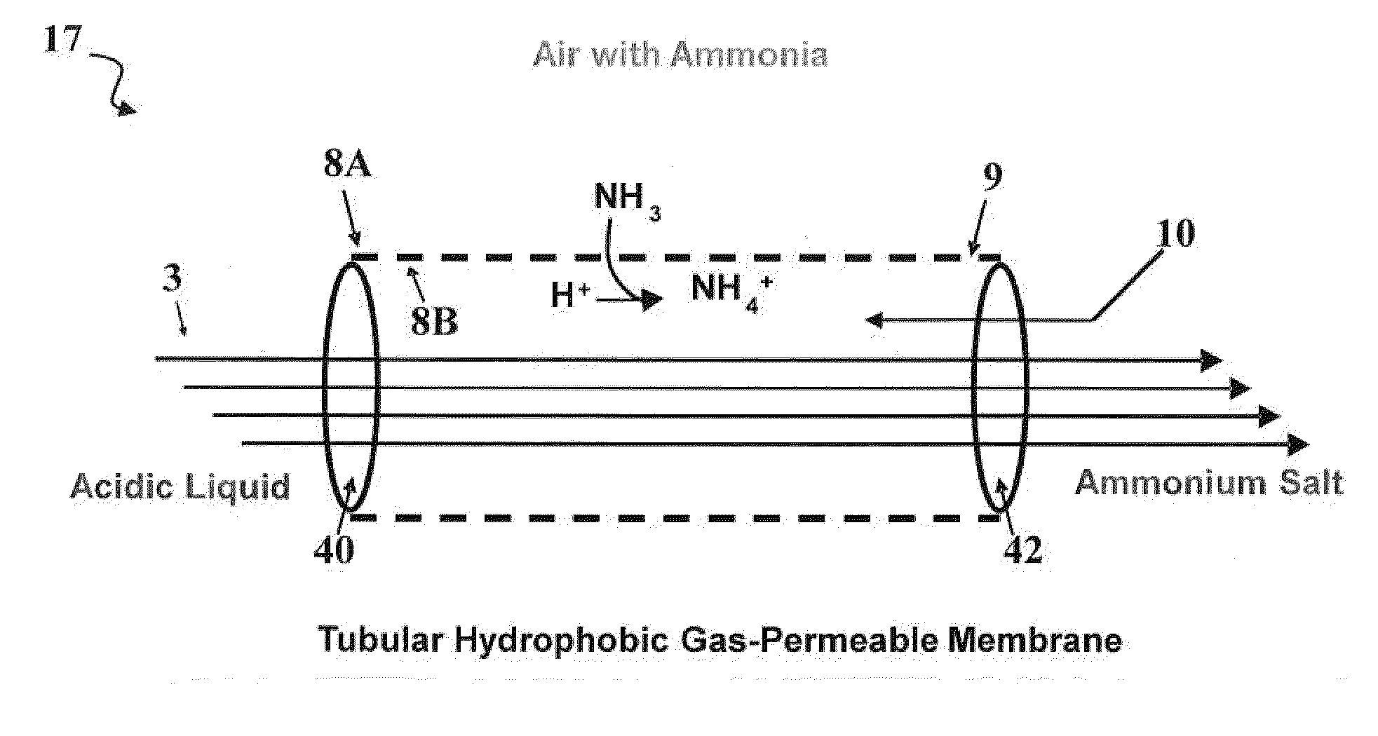
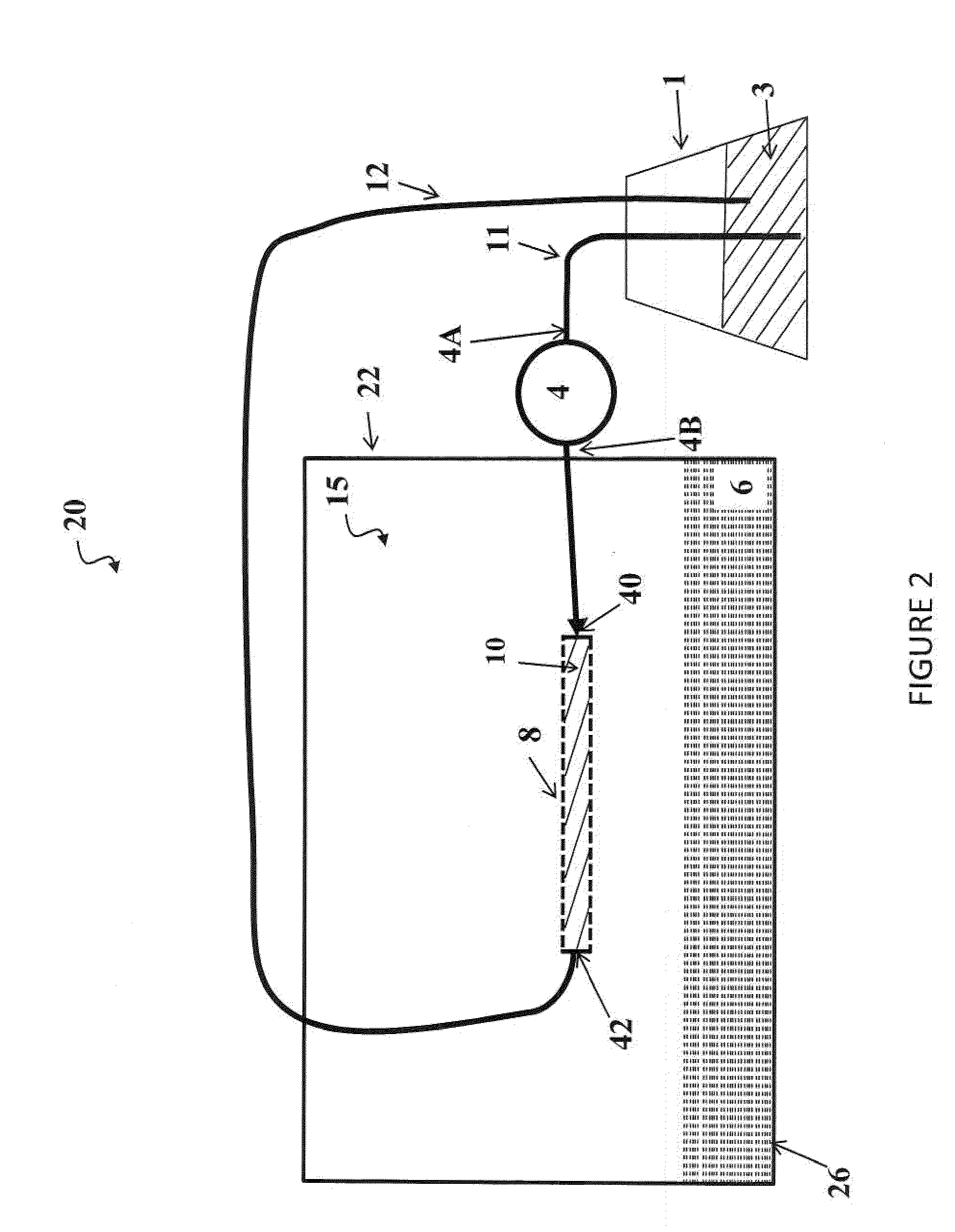
[0058]This example includes four experiments for the process configuration wherein an acid solution is contained in an acid tank and was continuously recirculated into a chamber containing poultry litter (See FIG. 2). Once inside the chamber, the acid was contained inside a microporous, hydrophobic gas-permeable, tubular membrane 8 allowing for the passage of NH3 gas emitted by the litter and subsequent recovery and concentration of the N as an ammonium salt.

[0059]FIG. 3 shows a 2-L, polyethylene terephthalate (PET) plastic, wide-mouth jar 18 cm (h)×12 cm (dia) with a threaded polyethylene lid (Cole-Palmer, Vernon Hills, Ill., USA). There were a total of five ports in the lid of the chamber, two for acid inflow-outflow, one for venting air, through tubing with glass wool, to ensure ambient pressure and aerobic conditions inside the chamber, and the remaining ports, allowed headspace air sampling (only the inflow-outflow ports are depicted). Tygon tubing (approximately 4.75 mm I.D., ...

experiment 1

[0065]The first experiment was designed to determine the general feasibility of using ePTFE tubular membranes on the recovery of NH3 released from poultry litter. Three different ePTFE tubings were tested (Table 1 and FIG. 4), and identified as A, B, or C; distinguished by the following properties. Tubing A possessed an inner diameter of 4.00 mm, a wall thickness of 0.25 mm, and a bubble point of 34.5 kPa. Tubing B possessed an inner diameter of 5.25 mm, a wail thickness of 1.00 mm, and a bubble point of 241.3 kPa. Tubing C possessed an inner diameter of 8.75 mm, a wall thickness of 0.75 mm, and a bubble point of 206.3 kPa. The membrane tubing inside the chamber had the same length (approximately 66 cm) but varied in terms of wall thickness, pore size, and bubble points. Placement of the ePTFE tubing was approximately 5 cm above the litter surface (shown in FIG. 5A).

[0066]The membrane system recovered about 96% of the NH3 lost from the litter during the 21 day evaluation (FIG. 6, Ta...

experiment 2

[0067]The second experiment was designed to determine if placement of the ePTFE tubing with respect to the litter surface had an effect on NH3 recovery. Type B ePTFE tubing (Table 1) was used for this experiment. The tubing was placed inside the chamber in the following three positions (FIG. 5): (A) Above: approximately 5 cm above the litter surface; (B) On: laying directly on the litter surface, and (C) Under: below the litter and inside a pocket made of 300-μm nylon mesh (Krystal Klear Filtration, Winamac, Ind.) to support the tubing under the weight of the litter.

[0068]The relative position of the tubular membranes (above, on, or under the litter) did not significantly affect the total mass of NH3 recovery by the system (FIG. 7A, p=0.4776) nor the mass of the NH4-N remaining in the litter after volatilization (FIG. 7B, p=0.7908). Therefore, the results of the three treatments were pooled together to perform a weekly mass balance of the NH4-N in the chambers (Table 4). In terms of...


PUM

PropertyMeasurementUnit
weightaaaaaaaaaa
aerodynamic diameteraaaaaaaaaa
lengthaaaaaaaaaa

Abstract

A system and method for passive capture of ammonia in an enclosure containing material that gives off ammonia. The invention allows for the passage of gaseous NH3 through microporous hydrophobic gas-permeable membranes and its capture in a circulated acidic solution with concomitant production of a concentrated non-volatile ammonium salt.

Description

[0001]This application claims priority to U.S. Provisional Patent Application Ser. No. 61 / 314,683, filed Mar. 17, 2010, the contents of which are incorporated herein by reference in their entirety.FIELD OF THE INVENTION[0002]This invention relates to a system and method for the removal of gaseous nitrogen and its conversion to non-volatile nitrogen-containing compounds to reduce emissions from systems that produce gaseous nitrogen.BACKGROUND OF THE ART[0003]One of the largest environmental concerns associated with raising poultry for production in confined enclosures is the accumulation of ammonia gas (NH3). Volatilization of NH3 inside poultry housing often results in an excessive accumulation of NH3 in the air, which can negatively affect the health of both workers and birds (Kirychuk et al., Journal of Occupational and Environmental Medicine 48 (7):741-748, 2006; Ritz et al., Journal of Applied Poultry Research 13:684-692, 2004; Rylander and Carvalheiro, International Archives of...

Claims


Application Information

Patent Timeline
Patent Type & Authority Applications(United States)
IPC IPC(8): C01C1/28C07C51/41C01C1/242B01J8/00
CPCB01D53/22B01D2251/50C07C51/412C01C1/28C01C1/242C01C1/185C01C1/164B01D2251/70B01D2257/406B01D2258/0266B01D2258/06C07C59/265C07C55/07C07C59/08C01C1/12
Inventor SZOGI, ARIEL A.VANOTTI, MATIAS B.ROTHROCK, MICHAEL J.
Owner US SEC AGRI
Why Eureka
Try Eureka