Ion beam assisted deposition of ophthalmic lens coatings

a technology of ophthalmic lenses and coatings, applied in the field of coatings for lenses, can solve the problems of reducing the brightness of transmitted light and reducing the contrast of transmitted images, and achieve the effect of reducing or preventing accumulation of static charges

Inactive Publication Date: 2011-09-22
LUXOTTICA US HLDG CORP
View PDF68 Cites 31 Cited by
  • Summary
  • Abstract
  • Description
  • Claims
  • Application Information

AI Technical Summary

Benefits of technology

[0036]At least one of the plurality of high refractive index layers can include a layer configured to reduce or prevent accumulation of static charge on the ophthalmic lens. The coating can include a topcoat layer disposed over the multilayer interference stack. The topcoat layer can be constructed from a hydrophobic material.

Problems solved by technology

The reflection of light in such circumstances can produce glare, decrease the brightness of transmitted light, reduce the contrast of a transmitted image, and produce other effects that can be disadvantageous.

Method used


Image

  • Ion beam assisted deposition of ophthalmic lens coatings
  • Ion beam assisted deposition of ophthalmic lens coatings
  • Ion beam assisted deposition of ophthalmic lens coatings

Examples


example coating

Configurations

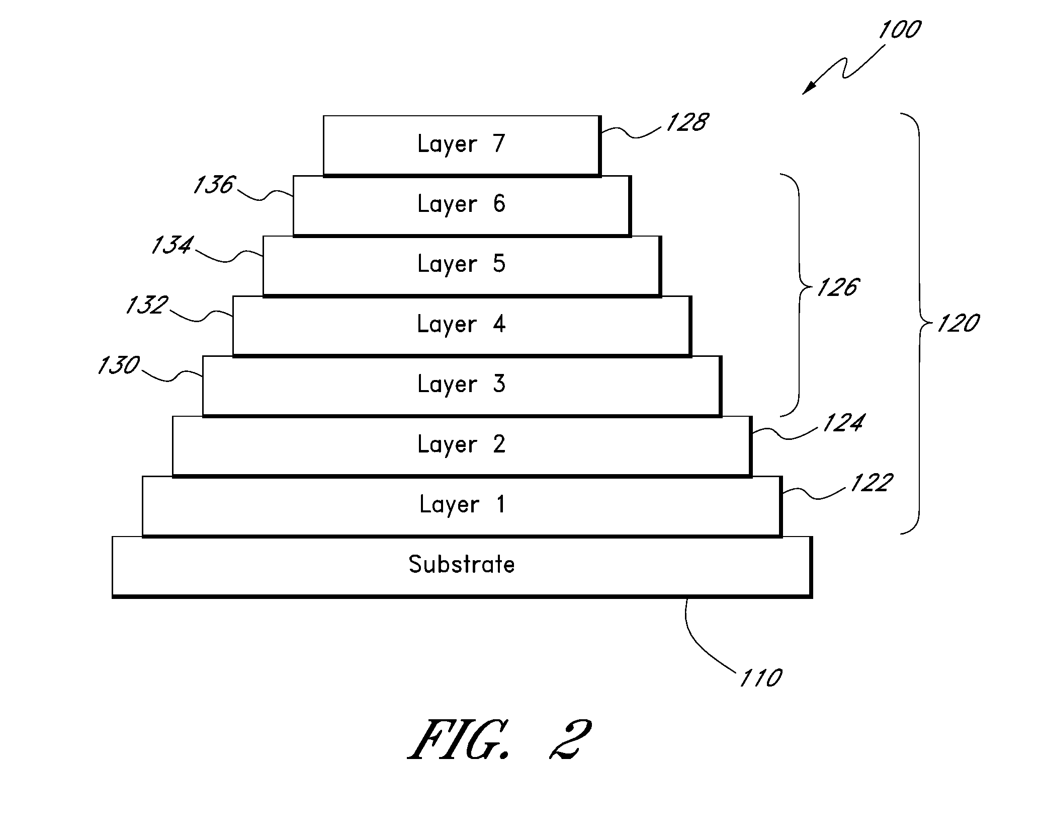
[0093]A first example coating configuration for a polycarbonate ophthalmic lens is shown in Table A. The structure of the example configuration is similar in many respects to the embodiment shown in FIG. 2, and the functional layer groups in the table are identified by corresponding reference numbers. Additional details regarding the layer materials, the thickness of each layer, the rate of deposit for each layer, whether IBAD is used during deposition of a layer, the ion energy of an End Hall ion source, and the process gas are provided in this example. The example also provides details for a clean step that can take place prior to deposition of the adhesor layer. During the clean step, the substrate can be contacted with ionized species of an inert gas, a reactive gas, or a mixture inert gas and reactive gas. In this example, the deposition process begins with the clean step and proceeds in order with deposition of the layers beginning with the adhesor layer 122 (nea...


PUM

PropertyMeasurementUnit
luminous reflectanceaaaaaaaaaa
thicknessaaaaaaaaaa
refractive indexaaaaaaaaaa

Abstract

Some embodiments provide a physical vapor deposition process for forming a coating on a substrate of an ophthalmic lens in a vacuum deposition chamber. The process can include depositing a multilayer interference stack having a plurality of low refractive index layers and a plurality of high refractive index layers on the substrate by: depositing one or more of the plurality of high refractive index layers by contacting the substrate with a vapor phase pulse of one or more high refractive index source chemicals simultaneously while contacting the substrate with an energetic ion beam generated by an ion source; and depositing each of the plurality of low refractive index layers by contacting the substrate with a vapor phase pulse of one or more low refractive index source chemicals.

Description

RELATED APPLICATIONS[0001]This application claims the benefit under 35 U.S.C. §119(e) of U.S. Provisional Patent Application Ser. No. 61 / 316,304, filed Mar. 22, 2010, titled ION BEAM ASSISTED DEPOSITION OF OPHTHALMIC LENS COATINGS, and of U.S. Provisional Patent Application Ser. No. 61 / 348,425, filed May 26, 2010, titled ION BEAM ASSISTED DEPOSITION OF OPHTHALMIC LENS COATINGS. The entire contents of each of these applications are incorporated by reference herein and made a part of this specification.BACKGROUND[0002]1. Field[0003]This disclosure relates to coatings for optical devices and in particular to coatings for lenses used in eyewear.[0004]2. Description of Related Art[0005]When light moves between media of differing refractive indices, both reflection and refraction of the light may occur. The reflection of light in such circumstances can produce glare, decrease the brightness of transmitted light, reduce the contrast of a transmitted image, and produce other effects that ca...

Claims


Application Information

Patent Timeline
Patent Type & Authority Applications(United States)
IPC IPC(8): C23C16/48C23C16/40C23C16/52
CPCC23C14/08G02B1/10C23C14/28G02C7/022
Inventor REYNOLDS, TIMOTHY RAY
Owner LUXOTTICA US HLDG CORP
Why Eureka
Try Eureka