Integrated multi-axis hybrid magnetic field sensor

a hybrid magnetic field and sensor technology, applied in the direction of magnetic measurement, instruments, measurement devices, etc., can solve the problems of increasing the cost of manufacturing, increasing the thickness of the final product, and not being well adapted to precisely control the geometry of the inclined plane of the structure, so as to avoid manufacturing complexity, low unit cost, and sufficient sensitivity

Inactive Publication Date: 2011-09-29
MEMSIC
View PDF15 Cites 58 Cited by
  • Summary
  • Abstract
  • Description
  • Claims
  • Application Information

AI Technical Summary

Benefits of technology

[0012]In such an arrangement, the three-axis sensors can provide sufficient sensitivity within a very low profile dev

Problems solved by technology

This particular orthogonal axis sensor mounting, however, can be technically challenging, and significantly increases the cost of manufacturing, as well as results in an increase in the thickness of the final product.
Microtechnology, however, is not well adapted to precisely control structure geometry on inclined planes, and renders the manufa

Method used


Image

  • Integrated multi-axis hybrid magnetic field sensor
  • Integrated multi-axis hybrid magnetic field sensor
  • Integrated multi-axis hybrid magnetic field sensor

Examples


third embodiment

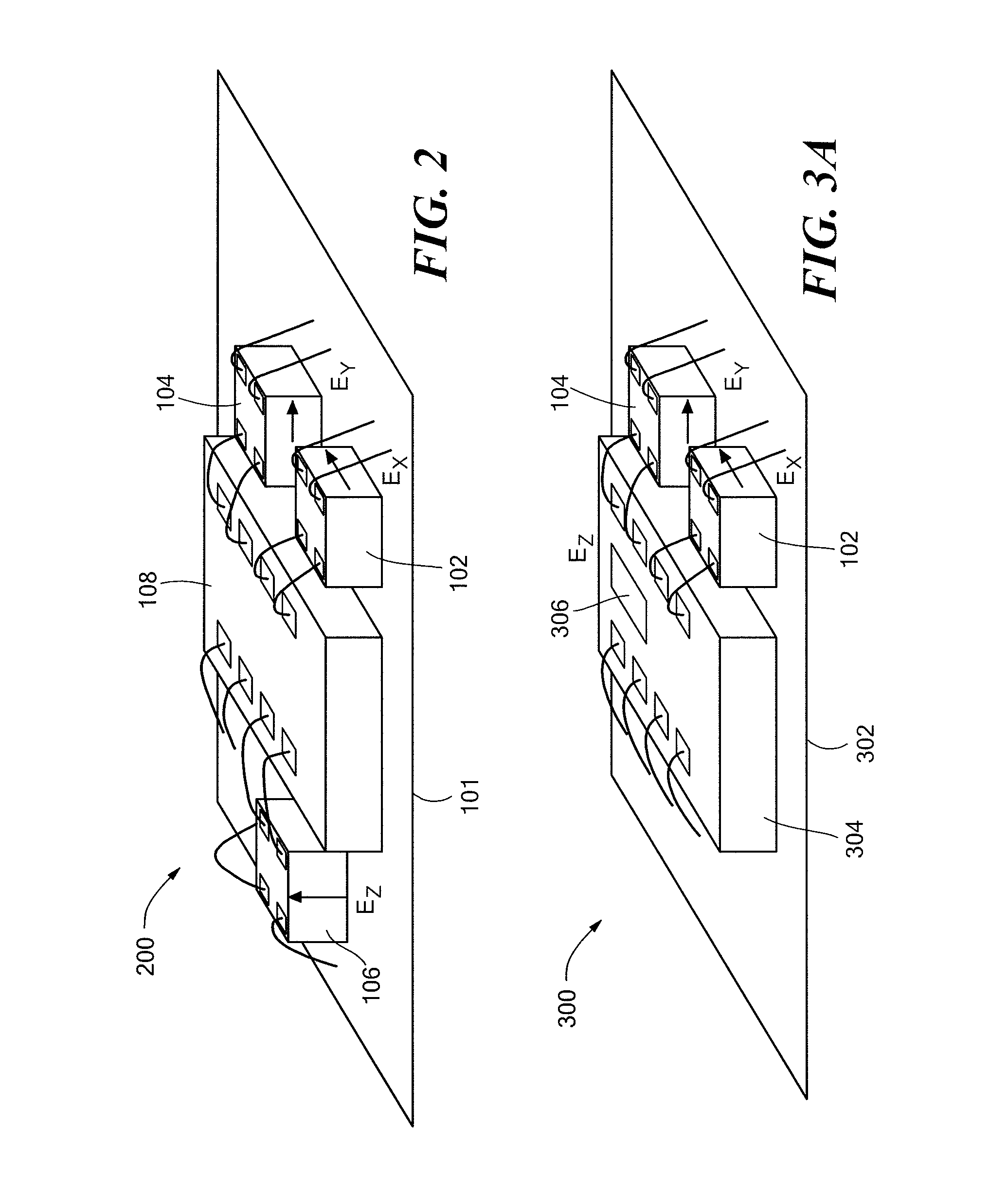
[0034]A three-axis magnetic field sensor system according to the present invention is presented in FIGS. 4A and 4B. In this embodiment, a system 400 includes an ASIC 402 having a Hall sensor element 306, integrated in the same way as the ASIC 304 shown in FIG. 3A, mounted on a PCB 403. A two-axis magnetoresistive device 404 that combines two sensor elements, each able to measure a respective component, Ex, Ey, of the magnetic field parallel to the plane made by the PCB 403 and orthogonal to each other, is provided. The magnetoresistive sensor 404 is mounted on top of the ASIC 402, commonly referred to as “stack packaging.”

[0035]Those skilled in the art will notice that such a sensor 404, combining two orthogonal magnetoresistive sensor elements, can be used in other embodiments of the present invention to replace the two magnetoresistive sensors.

[0036]Having a stack configuration, as shown in FIG. 4A, allows a further reduction of the lateral size of the system 400 while also keepin...

fourth embodiment

[0043]A schematic view of a magnetic field sensor system according to the present invention will now be described with respect to FIGS. 6A and 6B. A three-axis system 600 comprises a PCB 602 on which is mounted an ASIC 604. The ASIC 604 includes the electronic circuits for excitation and signal processing of the three sensors elements: a Hall sensor element 306 sensitive to the magnetic axis Ez orthogonal with respect to the plane defined by the PCB 602, and two Hall element switches 606.1, 606.2, able to, respectively, measure the directions of the magnetic field components Ex and Ey parallel to the plane of the PCB 602 and orthogonal to one another. A magnetoresistive sensor 608 is stacked on top of the ASIC 604 using the flip-chip method via solder balls 508. The MR sensor 608 integrates two magnetoresistive sensors that are each sensitive to a magnitude, but not the direction, of the respective component of the magnetic fields Ex, Ey parallel to the plane of the PCB 602 and orth...


PUM


Abstract

A multi-axis magnetic field sensing device combines two magnetoresistive sensors to measure the two orthogonal components X, Y of a magnetic field parallel to a system's plane and a Hall sensor to measure the Z component of the magnetic field substantially perpendicular to the system's plane. The two magnetoresistive sensors may be built together in one single chip and then stacked on top of a CMOS die embedding the Hall sensor and associated electronics for the signal processing management of the three sensors and the system's interface.

Description

STATEMENT REGARDING FEDERALLY SPONSORED RESEARCH OR DEVELOPMENT[0001]N / ABACKGROUND OF THE INVENTION[0002]Sensors to detect the earth's local magnetic field have been proposed and produced in large volume in the past. Some of these sensors feature two-axis sensing, while more sophisticated ones feature three-axis sensing. Different technologies are commonly used to detect such low strength magnetic fields. One of the two most common type of sensor is the magnetoresistive (MR) sensor.[0003]The construction of a magnetoresistive sensor is well known where, generally, the resistivity of the sensor varies according to a local magnetic field oriented in the same plane as the magnetoresistance. “Barber-pole” structures are added to allow a sensing of the magnetic field along one axis to include direction, or vector, information. Magnetoresistive sensors have been used successfully in electronic compass applications, using two sensors to detect the magnetic field in the same plane as the su...

Claims


Application Information

Patent Timeline
IPC IPC(8): G01R33/02G01R33/07
CPCG01R33/072H01L2224/48137H01L2224/48145H01L2224/16145
Inventor LAGOUGE, MATTHIEU
Owner MEMSIC
Why Eureka
Try Eureka