Remote Power Controller with Parallel FETS

a technology of remote power controller and parallel fet, which is applied in the direction of process and machine control, pulse technique, instruments, etc., can solve the problems of large power dissipation of fet and greatly reduced energy (soa) capability of smaller fet, so as to achieve lower safe operating area, reduce resistance at saturation, and reduce the effect of safe operating area

Inactive Publication Date: 2011-09-29
HAMILTON SUNDSTRAND SPACE SYST INT
View PDF7 Cites 1 Cited by
  • Summary
  • Abstract
  • Description
  • Claims
  • Application Information

AI Technical Summary

Benefits of technology

[0005]According to one aspect of the invention, a remote power controller (RPC) includes a line connection; a load connection; a first field effect transistor (FET) and a second FET arranged in parallel between the line connection and the load connection, wherein the first FET has a lower safe operating area (SOA) than a SOA of the second FET, and wherein the first FET has a lower resistance at saturation (RDS(on)) than the second FET; and a voltage offset element connected between the first FET and the second FET, such that in the event a current in the RPC is above a current limiting setpoint, the voltage offset element is configured to cause the first FET to turn off.
[0006]According to another aspect of the invention, a method of operating a remote power controller (RPC), the RPC comprising a line connection, a load connection, and a first field effect transistor (FET) and a second FET arranged in parallel between the line connection and the load connection, wherein the first FET has a lower safe operating area (SOA) than a SOA of the second FET, wherein the first FET has a lower resistance at saturation (RDS(on)) than the second FET, includes in the event that a current in the RPC is below a current limiting setpoint, turning the first FET on, and turning the second FET on; and in the event that a current in the RPC is above the current limiting setpoint, turning the first FET off.

Problems solved by technology

Therefore, the FET must dissipate a large amount of power during the fault.
Some FETs, which may be relatively small, are designed for switching applications and can achieve much lower RDS(on) values; however, the smaller FETs may have greatly reduced energy (SOA) capability.

Method used


Image

  • Remote Power Controller with Parallel FETS
  • Remote Power Controller with Parallel FETS
  • Remote Power Controller with Parallel FETS

Examples


Embodiment Construction

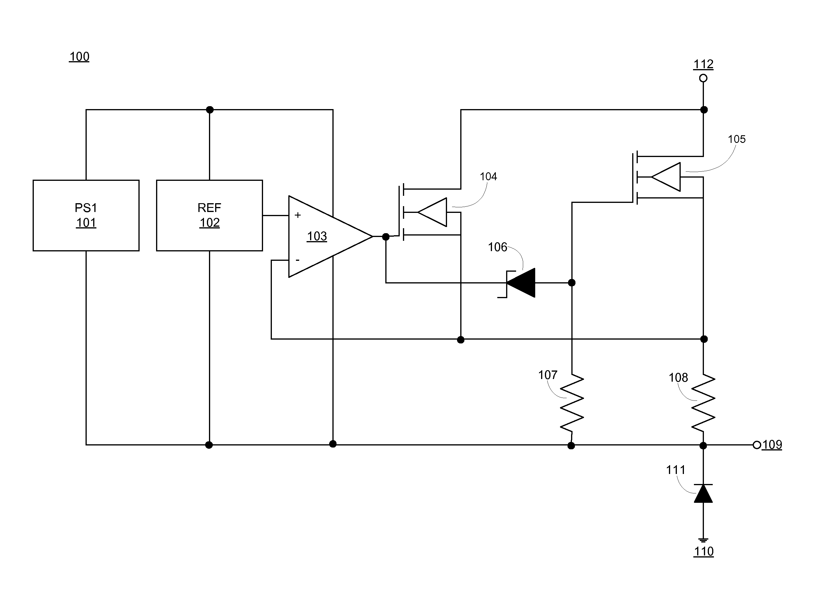
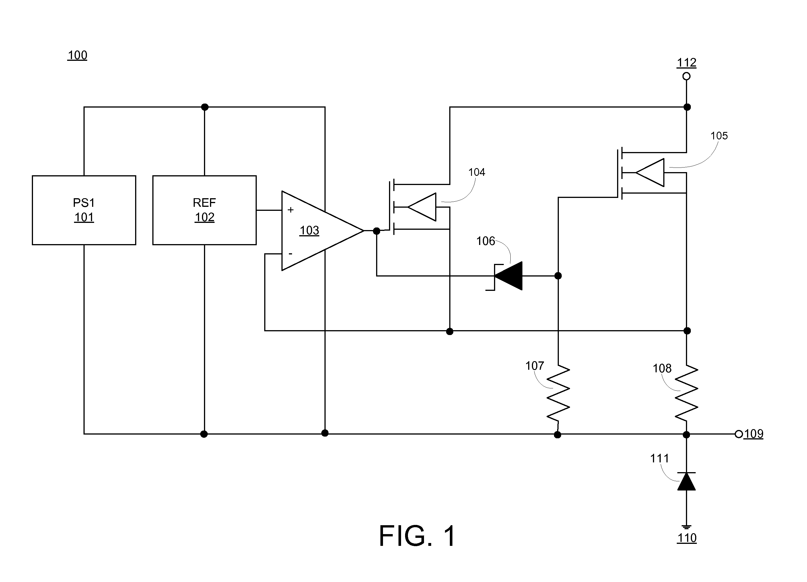
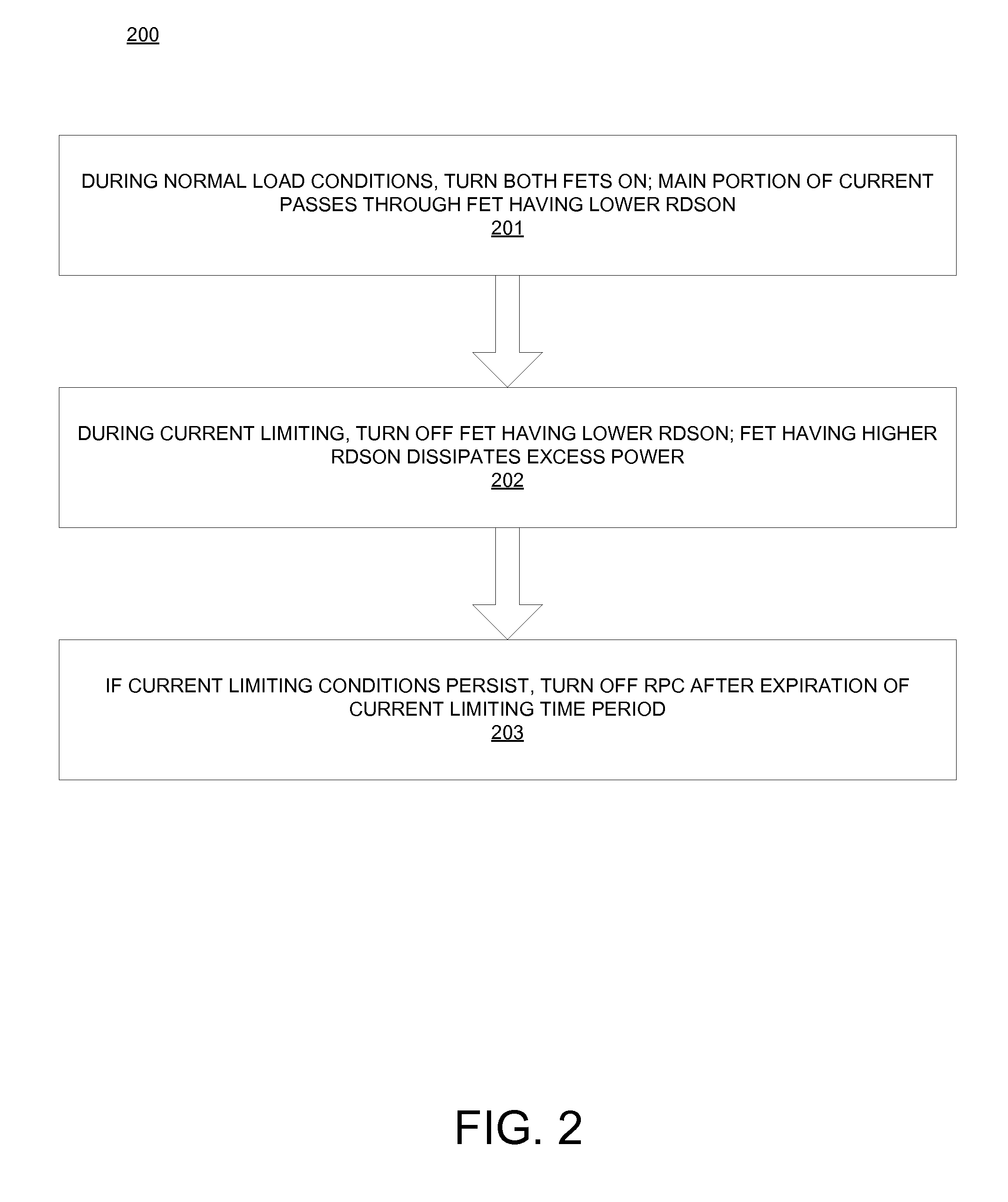
[0012]Embodiments of systems and methods for an RPC with parallel FETs are provided, with exemplary embodiments being discussed below in detail. An RPC may comprise parallel FETs, each FET being of a different type. Use of parallel FETs having different characteristics in an RPC may reduce the load on each individual FET to a sustainable level. One of the FETs may be selected for use during normal operating conditions, and the other may be selected for current limiting or dissipation of overload conditions.

[0013]FET characteristics include safe operating area (SOA) and RDS(on). The SOA defines the power and energy handling capability of a FET. The SOA defines a range of drain current values and a range of drain to source voltage values that the FET is able to handle for a certain time without damage. Both the drain current and the drain to source voltage in operation must stay below their respective maximum values for safe operation of the FET, and the product of the drain current a...


PUM


Abstract

A remote power controller (RPC) includes a line connection; a load connection; a first field effect transistor (FET) and a second FET arranged in parallel between the line connection and the load connection, wherein the first FET has a lower safe operating area (SOA) than a SOA of the second FET, and wherein the first FET has a lower resistance at saturation (RDS(on)) than the second FET; and a voltage offset element connected between the first FET and the second FET, such that in the event that a current in the RPC is above a current limiting setpoint, the voltage offset element is configured to cause the first FET to turn off.

Description

FIELD OF INVENTION[0001]The subject matter disclosed herein generally to the field of remote power controllers.DESCRIPTION OF RELATED ART[0002]A remote power controller (RPC) is a solid state device that controls and protects a power connection to an electrical load. RPCs may be found in complex electrical systems, including but not limited to aircraft or spacecraft electrical systems. RPCs allow switching to be performed at the load, instead of at the power source, reducing the complexity of the overall electrical system. An RPC acts to control the application of power to the load, and may also act as a fuse or circuit breaker, protecting electrical equipment from fault or overload conditions. For DC power applications, an RPC may be designed to limit the current to a prescribed level to protect the power distribution system.[0003]An RPC may comprise a metal oxide semiconductor field effect transistor (MOSFET or FET) having a relatively high power capability and a low voltage drop....

Claims


Application Information

Patent Timeline
Patent Type & Authority Applications(United States)
IPC IPC(8): H02H3/087
CPCH03K17/063H03K17/122H03K17/0822G05F1/66G05F3/24
Inventor FOX, DAVID A.
Owner HAMILTON SUNDSTRAND SPACE SYST INT
Why Eureka
Try Eureka