Adjustable Bolster Swing Legs for Mounting and Aligning and Reorienting Crawlers for Slipform Paving Machines

a technology of bolster swing legs and crawlers, which is applied in the direction of roads, highway maintenance, transportation and packaging, etc., can solve the problems of unsatisfactory deviation, the distance between the point of connection, the actuator to the tractor frame and the bolster swing leg can exceed the effective length of the turnbuckle or hydraulic actuator, and achieves high maneuverability on site. , the effect of reducing the time required to prepar

Active Publication Date: 2011-09-29
GUNTERT & ZIMMERMAN CONSTR DIV
View PDF13 Cites 74 Cited by
  • Summary
  • Abstract
  • Description
  • Claims
  • Application Information

AI Technical Summary

Benefits of technology

[0019]A still further aspect of the present invention eliminates the need to reposition the steering cylinder on the jacking columns when the crawler track is repositioned within the range of the swing leg cylinder and to allow 90° steering without having to reposition the steering cylinder by employing a hydraulic motor driven rotary actuator (slew gear) with an angular position transducer as the power drive between the crawler track and the jacking column. The rotary actuator also allows a wide range of steering angles while in the 90° steering mode to make the machine highly maneuverable on site. Working in conjunction with the swing leg position transducer, and after unpinning the swing leg hydraulic cylinder from the swing leg, the rotary actuators allow the machine to be preprogrammed to first turn the crawler tracks relative to the jacking columns normal to the paving direction, and then walk the crawler tracks on the ground in an arc around the pivot shaft of the swing legs into their outboard transport position (in which the crawlers are oriented 90°, i.e. substantially transverse to the paving direction) so that the paving machine can be sufficiently narrowed for moving it over ordinary highways to a new paving site with a legal or otherwise approved transport width dimension, or, for maneuvering the paving machine around a paving site which is tightly confined. The heretofore common need to manually move the swing legs with jacking columns and crawler tracks into the outboard position as previously described is thereby eliminated, which significantly reduces the time required to ready the machine for transport and / or for maneuvering the machine at the work site.
[0020]Thus, a paving machine constructed in accordance with the present invention has a main frame that includes a center module, a side bolster that is laterally movably connected to respective lateral sides of the center module for changing a spacing between the bolsters, a crawler track associated with respective aft and forward ends of the bolsters, and a bolster swing leg for each crawler track. An upright jacking column is secured to the free end of the swing leg, and a connection between the jacking column and the crawler track permits rotational movements of the crawler track and the jacking column about an upright axis. A hinge bracket is interposed between each swing leg and an associated surface of the bolsters and includes a fixed, upright pivot shaft that pivotally engages the swing leg for pivotal movements in a substantially horizontal plane. The hinge plate includes a pivot pin that is laterally spaced from and fixed in relation to the pivot shaft. A length-adjustable, preferably hydraulically actuated, holder is capable of being held at a fixed length and has a first end that pivotally engages the pivot pin and a second end that pivotally engages the swing leg. The holder permits pivotal motions of the swing leg about the hinge pin when in its length-adjustable configuration and prevents substantially any motion of the swing leg when the holder is in its fixed-length configuration.

Problems solved by technology

If this angular inclination becomes too small, the turnbuckles / hydraulic actuators lose effectiveness and rigidity, which, if permitted to occur, can lead to undesired deviations in the desired orientation of the crawler tracks, and if the inclination becomes too large, the distance between the point of connection of the turnbuckles / hydraulic actuators to the tractor frame and to the bolster swing leg can exceed the effective length of the turnbuckle or hydraulic actuator.
This was a time-consuming task that required skilled workers and, therefore, was costly.
In addition, the time it takes to change the position of the mounting bracket for the turnbuckle / hydraulic actuator is a downtime for the machine during which it is out of use and cannot generate revenues.
These clearances are undesirable because if the swing leg is allowed to pivot or tilt under varying loads, it can adversely affect steering and elevation control.
The drawback of this approach is that the outboard turnbuckles increase the overall machine profile outside the edge of concrete and therefore require more room for the machine when paving past obstacles in tight confines.
The relocation of the bolster swing leg and crawler track in relationship to the tractor frame is further adversely affected by the need to relocate the turnbuckle connection on the tractor frame where it connects to the bolsters to which the swing leg is attached.
In the past, the turnbuckle connection to the tractor frame posed several problems.
One such problem was when the tractor frame was telescoped narrower.
At wider tractor widths, the turnbuckle connects to the outboard end of the support beam of the tractor frame with a turnbuckle bracket that is bolted to the male support beam (that telescopes in and out of the tractor center module) with two or more bolts; however, if the tractor frame is telescoped narrower, the bracket will eventually interfere with the tractor center module, which prevents the further narrowing of the tractor frame.
The inboard turnbuckles can also interfere with other attachments required on the front and rear of the machine, such as a spreader plow that is mounted off the front of the tractor frame, which had to be disconnected and reconnected, which increases costs further.
Another problem was when the swing leg complete with jacking column and crawler track is relocated to the outside of the side bolster or mounted directly to the tractor center module, in some paving applications there was no place to connect the bolster swing leg or turnbuckles (hydraulic actuators).
The relocation of the bolster swing legs and crawler track in relationship to the tractor frame is further adversely affected by the steering cylinders that typically were used on the jacking columns.
This is undesirable because it increases the outside width of the paving machine, which dictates and will limit how close the machine can pave next to a building or obstruction, and the stroke of the steering cylinder dictates how far the swing leg can be swung inboard or outboard.
Amongst others, such a jacking column steering cylinder configuration does not allow the crawler tracks to be rotated 90° from their normal operating orientation without the time-consuming repinning or repositioning of the steering, which is a drawback.
This has to be repeated for each of the typically four crawlers of the paving machine, a process that is time-consuming, costly and results in a prolonged, unproductive downtime for the machine.
This cost is encountered each time the lateral position of the crawler and / or turnbuckle mounting bracket is changed and the crawlers must then be reoriented relative to the frame so that they face in the required transport direction.
However, in such arrangements, the limited range of movement of the parallel linkages with hydraulic actuator limits how narrowly the machine can be collapsed for transporting it over highways (with standard highway width restrictions) to new construction sites.
The ability to quickly and efficiently move the paving machine from one site to the next, which is highly desirable for the efficient use of the machine, is lost with this approach.
In either case, this could significantly increase the overall cost of the machine or the cost or time required for moving the machine and is therefore an undesirable alternative.
Of course, adding the pivot hinge with a pinning mechanism to each corner of the machine is costly, and pinning and unpinning of the hinge is time-consuming.

Method used


Image

  • Adjustable Bolster Swing Legs for Mounting and Aligning and Reorienting Crawlers for Slipform Paving Machines
  • Adjustable Bolster Swing Legs for Mounting and Aligning and Reorienting Crawlers for Slipform Paving Machines
  • Adjustable Bolster Swing Legs for Mounting and Aligning and Reorienting Crawlers for Slipform Paving Machines

Examples


Embodiment Construction

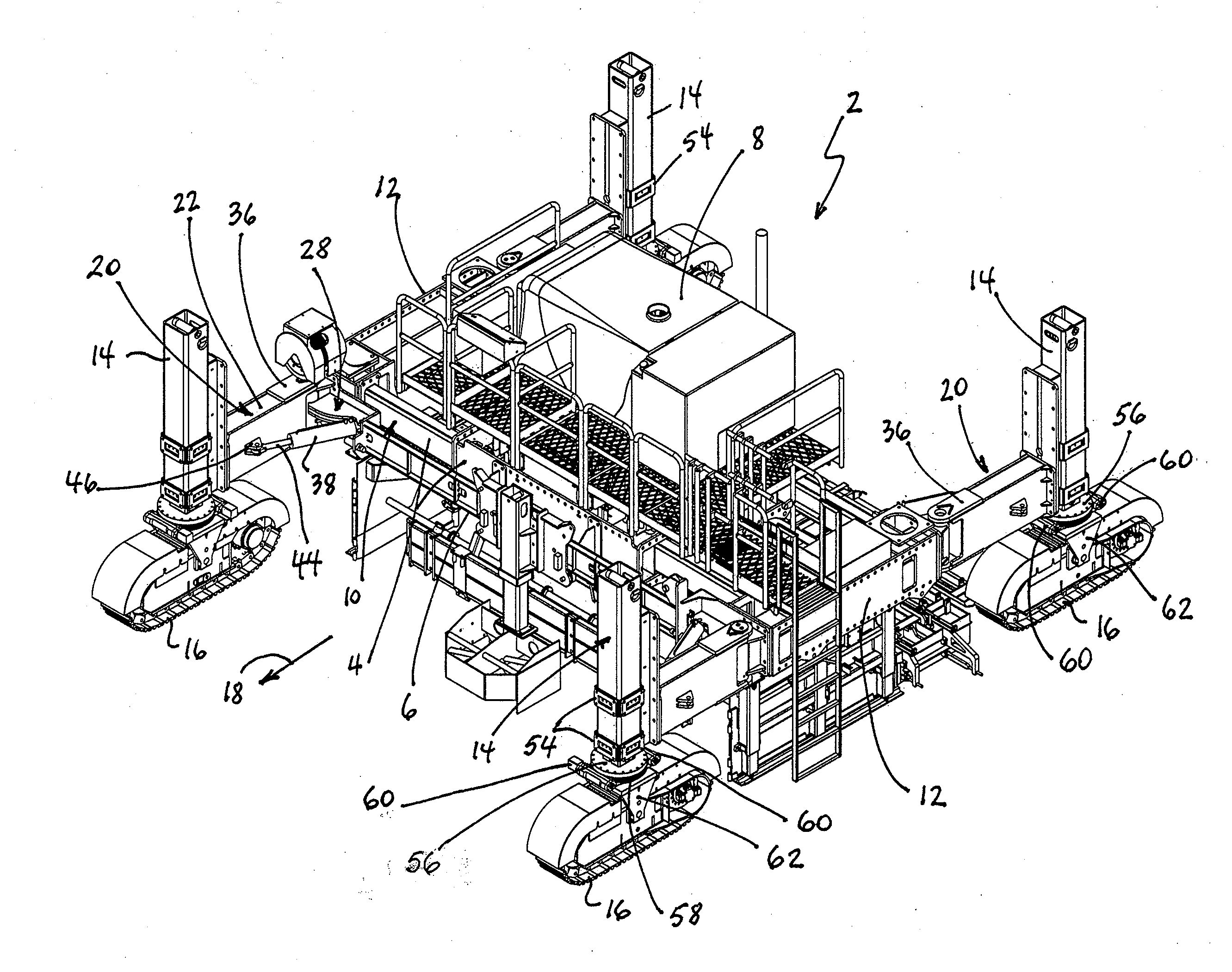
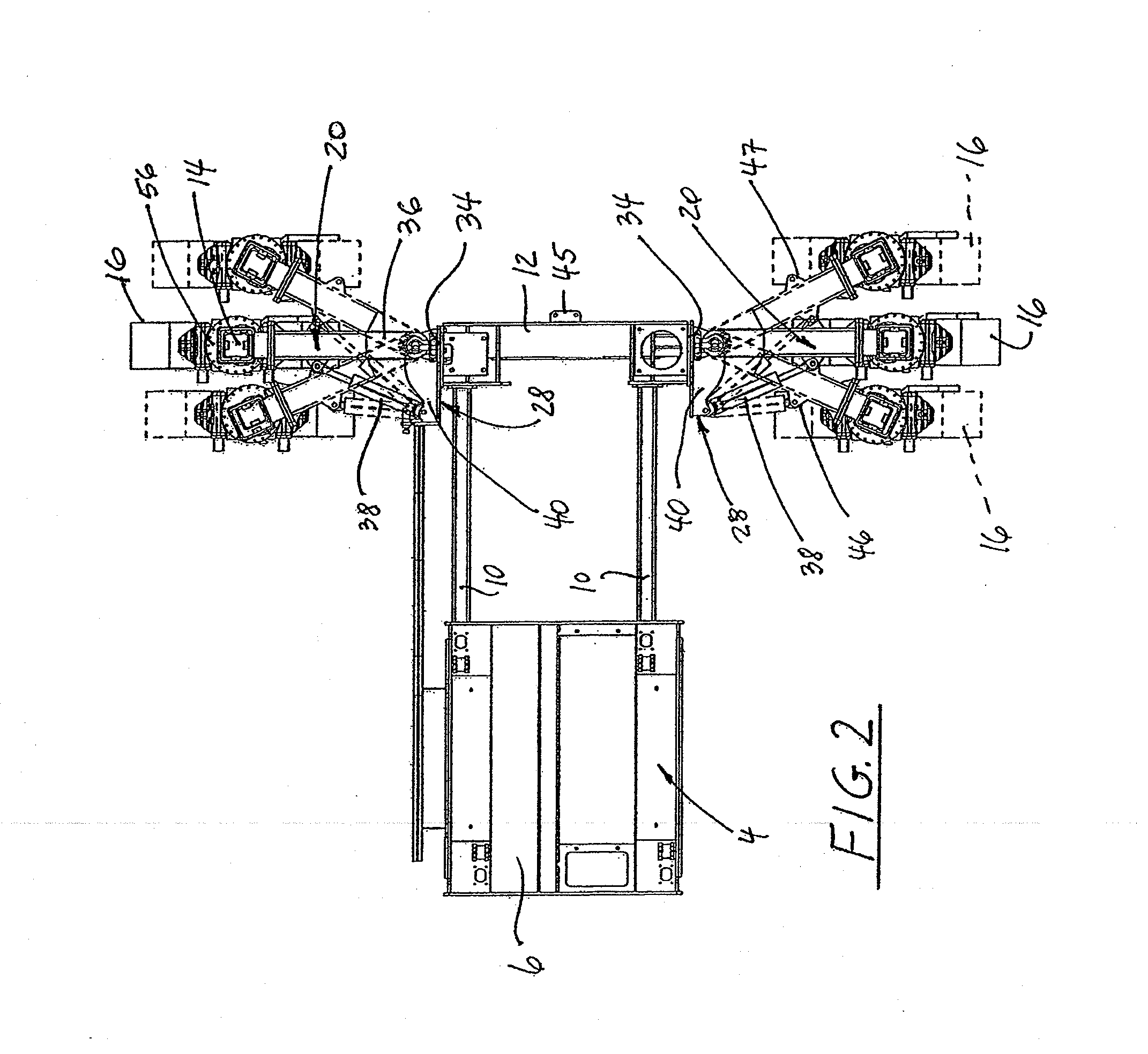
[0033]Referring initially to FIG. 1, a concrete slipform paving machine 2 has a main tractor frame 4 defined by a center module or platform 6 that carries the diesel engine powered power unit 8 of the paving machine and from which extendable or telescoping male support beams 10 extend outwardly in a lateral direction. Side bolsters 12 are secured to the respective outboard ends of the support beams. Upright jacking columns 14 are mounted in the vicinity of respective front and aft ends of the bolsters, and crawlers 16 are conventionally secured to the lower ends of the jacking columns. The jacking columns are hydraulically powered for raising and lowering of the paving machine relative to the crawlers on the ground. The crawlers are mounted to the lower ends of the jacking columns, and they are rotatable relative to the jacking columns about vertical axes, an arrangement that is known in the art. The crawlers support the entire machine and move it over the ground.

[0034]The respectiv...


PUM


Abstract

A paving machine which is configured to move in a paving direction for spreading, leveling and finishing concrete into a form having a generally upwardly exposed, finished concrete surface and terminating in lateral concrete sides. The paving machine has a main frame, including a center module, bolsters laterally movably connected to respective lateral sides of the center module for changing a spacing between the bolsters, and a crawler track associated with respective aft and forward ends of the bolsters. A bolster swing leg for each crawler track supports an upright jacking column secured to the swing leg proximate a free end thereof. A worm gear drive between the jacking column and the crawler track permits rotational movements of the crawler track and the jacking column about an upright axis. A hinge bracket is interposed between each swing leg and an associated surface of the bolsters and includes a fixed, upright pivot shaft that pivotally engages the swing leg to enable pivotal movements of the swing leg about an upright axis in a substantially horizontal plane. The hinge bracket further includes a pivot pin that is laterally spaced from and fixed in relation to the pivot shaft. A length-adjustable holder capable of being held at a fixed length has a first end pivotally engaging the pivot pin on the hinge bracket and a second end that pivotally engages the swing leg. The holder permits pivotal motions of the swing leg about the hinge pin when it is in its length-adjustable configuration and prevents substantially any motion of the swing leg when the holder is in its fixed-length configuration. A feedback loop cooperates with angular position transducers and automatically keeps the crawler tracks oriented in the paving direction of the machine when the swing legs move in a horizontal plane relative to a remainder of the paving machine. The paving machine can be reconfigured between its paving orientation and a road transport orientation by activating the crawlers to move the swing legs and the crawlers into a narrowed transport configuration.

Description

CROSS-REFERENCES TO RELATED APPLICATIONS[0001]This application claims the priority of U.S. Provisional Application No. 61 / 318,223, filed on Mar. 26, 2010, the disclosure of which is incorporated herein by reference.BACKGROUND OF THE INVENTION[0002]The present invention concerns concrete slipform paving machines that have a propelling unit or tractor from which a paving kit is suspended with which a layer of concrete is shaped and finished over the underlying ground as the tractor travels along a road or airfield alignment. The tractor of a concrete slipform paver has a rectilinear frame which straddles the concrete roadway or airfield pavement section that is being paved. The frame is propelled and supported on either end by crawler tracks mounted on side bolsters. These side bolsters each typically have two hydraulic supporting jacking columns, each of which connects to a crawler track, that allow the tractor frame elevation to be manually or automatically varied relative to the gr...

Claims


Application Information

Patent Timeline
Patent Type & Authority Applications(United States)
IPC IPC(8): E01C19/42E01C19/48E01C19/22
CPCE01C19/42E01C19/002E01C19/4853B62D55/065B62D55/084E01C19/48
Inventor GUNTERT, JR., RONALD M.DAHLINGER, GERALD L.FRANCIS, RICHARD WOOD
Owner GUNTERT & ZIMMERMAN CONSTR DIV
Why Eureka
Try Eureka