
Methods and Apparatus for Producing a Mass Spectrum

a mass spectrum and apparatus technology, applied in mass spectrometers, isotope separation, particle separator tubes, etc., can solve the problems of difficult or prohibitively expensive changes in the field geometry and voltage of orbitrap-ms, and the need for relatively long detection times to achieve high resolving power, etc., to achieve a simple and robust method

Active Publication Date: 2011-10-06
THERMO FISHER SCI BREMEN
View PDF0 Cites 46 Cited by
  • Summary
  • Abstract
  • Description
  • Claims
  • Application Information

AI Technical Summary

Benefits of technology

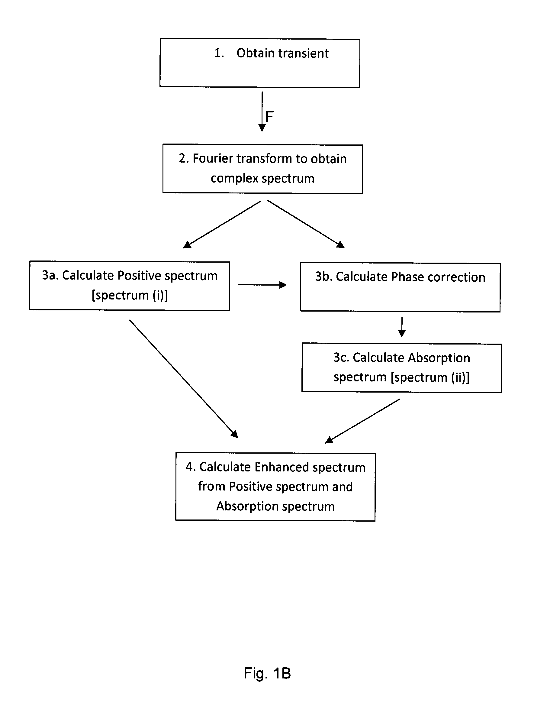
The present invention provides a method and apparatus for producing a high-resolution mass spectrum with enhanced resolution compared to the magnitude spectrum. This is achieved by Fourier transforming a transient obtained from the oscillation of ions in a mass analyzer and calculating an enhanced spectrum which comprises a combination of (i) and (ii) where (i) is a Positive spectrum obtained from the complex spectrum and (ii) is an Absorption spectrum obtained from the complex spectrum. The enhanced resolution can be used to increase the speed of a mass spectrum acquisition while maintaining a given resolution. The invention also reduces the problem of sidelobes and spectral leakage, resulting in more information being retained in the mass spectrum. The mass analyzer used in the invention can be any FT mass analyzer, such as an FT-ion trap, an FT-ICR mass analyzer, or an electrostatic orbital trapping mass analyzer.

Problems solved by technology

Fourier transformation of the digitised transient is a fast processing method but requires relatively long detection times to achieve high resolving powers.
However, there exist obstacles to the improvement of resolving power.
Technical solutions like e.g. increase of the magnetic field in FT-ICR-MS or changes to the field geometry and voltages of an Orbitrap-MS may be difficult or prohibitively expensive.
Without perfect phase correction a lessening of peak position accuracy is caused by the phase variation with frequency of the various components constituting the transient which results, e.g., from the typical time delays inherent between excitation and / or injection of ions into the mass analyser and the start of detection of the transient.
This phase variation problem produces asymmetrical peak shapes for the real component following the Fourier transformation.
The use of the magnitude spectrum, which amounts to disregarding the phase information, yields symmetrical peaks in the frequency / mass spectra but suffers from reduced resolving power compared to the pure absorption spectrum.
However, the approach described in U.S. Pat. No. 7,078,684 is not useful in the case of electrostatic orbital trapping mass spectrometers like the Orbitrap™ mass analyser operated without excitation but instead with excitation-by-injection, since current ion injection methods for injecting ions into the mass analyser involve changing the trapping field during injection so that the oscillation frequencies of the ions during this initial injection period are also changing.
In the case of the Orbitrap™ mass analyser therefore, the time delay between ion injection and detection is difficult to minimise.
Additionally the method of U.S. Pat. No. 7,078,684 proves, regardless of analyser type, to suffer from sidelobe problems (discussed further below) and mass accuracy problems relating to the limited quality of phase correction.
However, a problem of simply applying a phase correction to the data is that transformed peaks in the resultant frequency or mass spectra suffer from a problem of spectral artefacts such as large sidelobes beside peaks and a baseline curve or roll can be introduced.
Sidelobes can be a particular problem if a second or further peak is in the position of one of the sidelobes and so becomes disturbed or even lost from the spectrum.
These problems are inherent in the methods described above and the solution in those methods is to hide the appearance of sidelobes in the spectrum by use of “half-Hanning” apodisation and accept a high degree of spectral leakage, leading to distortion of neighbouring peaks over a broader region and an overall increase in “noise”.
In addition, the sidelobe problem is not really solved but just hidden under the spectral leakage of other peaks.
The displayed data may also be subject to baseline clipping which improves the appearance of the spectra but also leads to errors.
Another negative impact of a simple linear phase correction is to reduce mass accuracy due to mass dependent phase variations which is not addressed by those methods.
A problem with windowing or apodisation, however, is that the transformed peak becomes broadened, i.e. the resolving power is lessened.

Method used


Image

  • Methods and Apparatus for Producing a Mass Spectrum
  • Methods and Apparatus for Producing a Mass Spectrum
  • Methods and Apparatus for Producing a Mass Spectrum

Examples


Embodiment Construction

[0126]In order to more fully understand the invention, it will now be described in more detail with reference to the accompanying Figures in which:

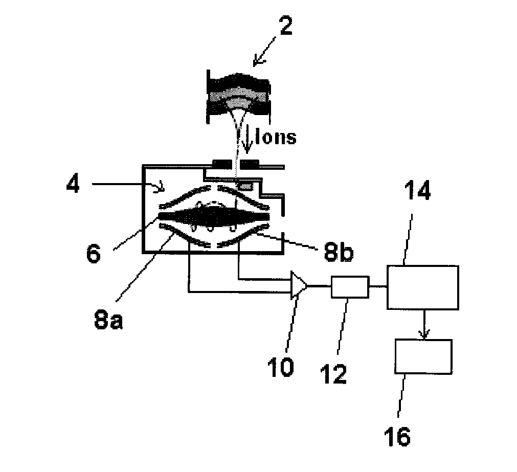
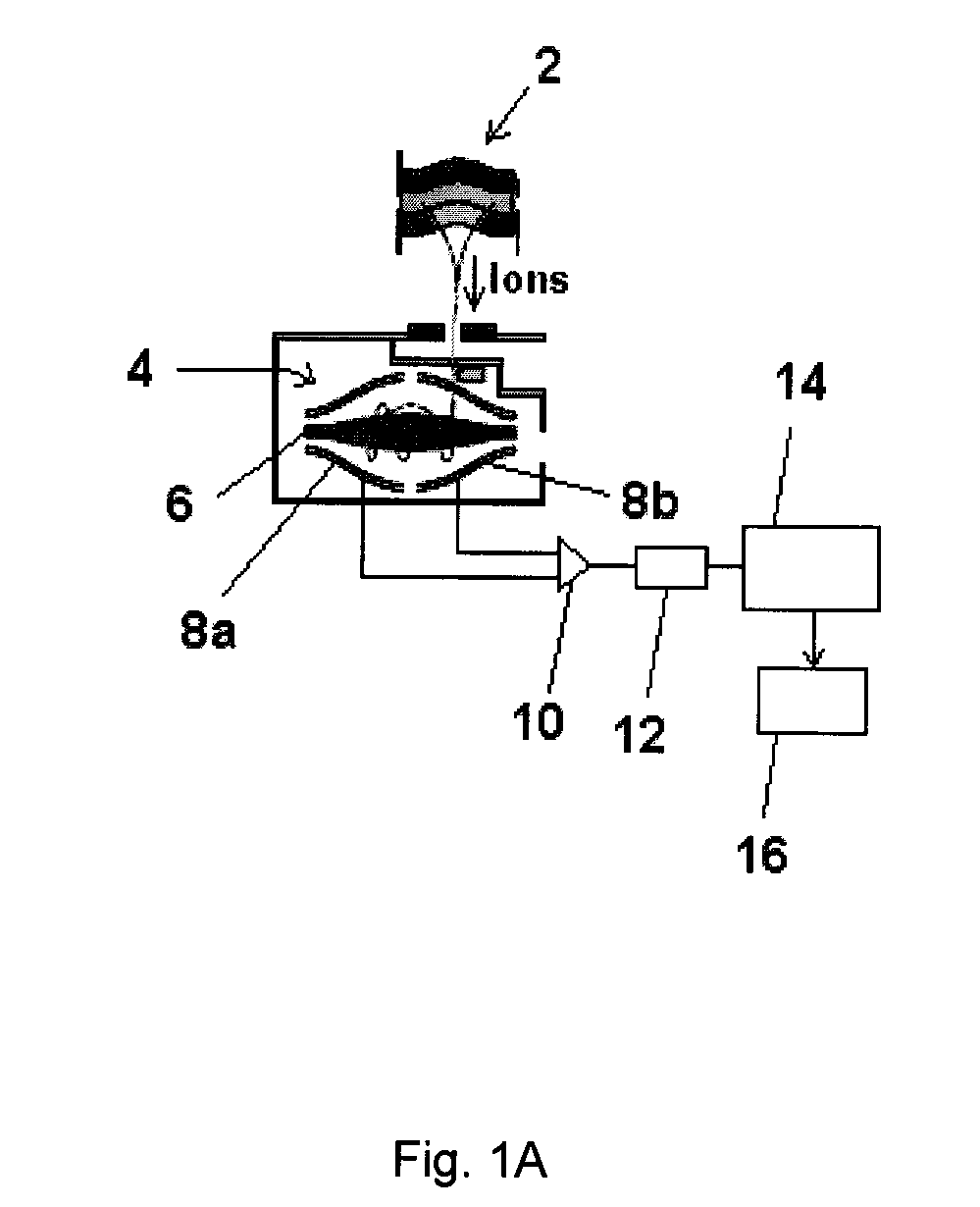
[0127]FIG. 1A shows schematically part of an apparatus according to the present invention;

[0128]FIG. 1B shows a schematic flow diagram of an example of a method according to the present invention;

[0129]FIG. 2A shows an “ideal” transient for just a few oscillations of a single frequency (m / z) component;

[0130]FIG. 2B shows a transient for just a few oscillations of a limited number of frequency (m / z) components;

[0131]FIG. 3 shows the Fourier transformation of the ideal single frequency signal shown in FIG. 2A together with the magnitude mode spectrum;

[0132]FIG. 4 shows a plot of several individual transient components and their phase coincidence at t0;

[0133]FIG. 5 shows a plot of the deviation of the phases of multiple transient components as a function of delay time, ttest;

[0134]FIG. 6, shows a plot of the phase against frequency for selec...


PUM


Abstract

The invention provides a method of producing a mass spectrum, comprising:obtaining a transient from the oscillation of ions in a mass analyser;Fourier transforming the transient to obtain a complex spectrum having a real component and an imaginary component; andcalculating an enhanced spectrum which comprises a combination of (i) and (ii) wherein(i) comprises a Positive spectrum; and(ii) comprises an Absorption spectrum.Also provided are an apparatus for producing a mass spectrum suitable for carrying out the method as well as a method of determining a phase correction for a complex spectrum obtained by Fourier transformation from a detected transient obtained from a mass analyser.

Description

FIELD OF THE INVENTION[0001]This invention relates to methods and apparatus for producing mass spectra, particularly but not exclusively high resolution mass spectra that are produced by means of a Fourier transform. The invention is preferably though not of necessity partially implemented in computer software.BACKGROUND OF THE INVENTION[0002]The use of Fourier transforms is a well known and established data processing technique enabling high resolution mass spectra to be obtained from mass spectrometers which acquire data in the form of a transient, for example by detection of an induced oscillating image current. The technique will be referred to herein as Fourier transform mass spectrometry (FTMS) and description of the technique can be found, for example, in Marshall, A. G. & Verdun, F. R., Fourier Transforms in NMR, Optical and Mass Spectrometry; A User's Handbook, Elsevier, 1990. Examples of such mass spectrometers include Fourier transform ion cyclotron resonance (FT-ICR) mas...

Claims


Application Information

Patent Timeline
Patent Type & Authority Applications(United States)
IPC IPC(8): H01J49/34H01J49/10
CPCH01J49/425H01J49/0036
Inventor LANGE, OLIVER
Owner THERMO FISHER SCI BREMEN
Learn More