Radiation Sterilization of Implantable Medical Devices

a medical device and implantable technology, applied in the field of medical devices, can solve the problems of reducing so as to reduce and minimize the radiation dose variance

Inactive Publication Date: 2011-10-06
ABBOTT CARDIOVASCULAR
View PDF21 Cites 2 Cited by
  • Summary
  • Abstract
  • Description
  • Claims
  • Application Information

AI Technical Summary

Benefits of technology

[0013]One example of an implantable medical device particularly suited for radiation sterilization according to the invention is a drug-eluting polymer stent. It has been observed that e-beam radiation of polymer stents can result in cracking of struts during deployment due to onset of brittle behavior. The cracking can be due to a reduction in molecular weight. Additionally, the increase in temperature can result in a loss of some or all of the induced orientation and strength due to relaxation of polymer chains. Furthermore, radiation, which increases the temperature of the stent, can increase the release rate of drug resulting in a decrease of drug loading on a stent. Therefore, the modification of polymer properties due to radiation is generally due the reactions which are chemical in nature as well as the increase in temperature of a sample. Thus, by reducing the dose level at any location on the medical device, there will be reduced rate of loss of molecular weight, or greater control over molecular weight loss, and / or alterations in the release rate of a drug contained within a polymer coating. Accordingly, greater control and predictability over the performance of the polymer stent when implanted within a body is possible when practicing the methods of the invention.
[0014]The problems in the art addressed by the invention are two-fold, but related. Typical bioburden levels for an implantable medical device require at least 25 kGy to reduce the bioburden on the device to the required SAL of 10−6. In prior years, the upper limit for radiation dosages has been upwards of 100 kGy. This afforded a wide operating range for making adjustments or operating the radiation source, e.g., an electron beam, without requiring precise control over beam parameters, conveyor speed, etc. More recent trends in medical devices, especially the development of drug-eluting bio-absorbable polymer stents (as described above), however, have required the upper dose limit to be significantly lowered to avoid causing damage to the device. Typical upper ranges for a drug-eluting bio-absorbable polymer stent are now 30 kGy or less. This significantly reduces the available operating range, which increases the complexity of the sterilization procedure because greater control over the speed of the device as it passes through the radiation source, and beam parameters is required. Similarly, the more narrow range required now makes it more difficult to maintain a sufficient level of throughput, i.e., time required to sterilize each device. Moreover, when operating within more narrow ranges, even assuming more precise control is feasible, there is greater risk that the maximum allowable dose will be exceeded since dose levels approach upper limits more often than in the past.
[0015]In view of the foregoing, methods are provided to reduce variance in radiation dosages received over a medical device by adjusting dosage levels with orientation of the medical device relative to a radiation source. For example, for a first pass the medical device is disposed in a first orientation, e.g., front facing the radiation source, and then exposed to radiation at a first dose level. For a second pass the medical device is disposed in a second orientation, e.g., back facing the radiation source, and then exposed to radiation at a second dose level, different from the first dose level. The dose levels are selected so as to arrive at a total radiation exposure, meaning the sum total of radiation received when the first dose is administered and the radiation received when the first dose is administered, for the medical device that best minimizes differences between doses received at different locations on the medical device. With variance in dose minimized over the device, there is a greater operating range made available, which simplified the sterilization process and reduces instances where does levels approach maximum allowable limits for the device.
[0024]The N dose level and / or N directions are selected so that the difference in total radiation throughout the medical device is minimized. Alternatively, the N dose level and / or N directions may be chosen to minimize the differences between a minimum and a maximum dose, e.g., difference between two dosimeter readings, as opposed to an overall minimization of differences. In some embodiments the N dose levels may be the same. In other embodiments, both the dose levels and the orientations are adjusted to produce a minimal variance. The integer N may be less than 10, or 2, 3, 4 or 6. The dose levels may be adjusted for one or more of the N orientations according to the density of material in a high dose zone for the respective orientation relative to the other orientations.INCORPORATION BY REFERENCE

Problems solved by technology

It has been observed that e-beam radiation of polymer stents can result in cracking of struts during deployment due to onset of brittle behavior.
Additionally, the increase in temperature can result in a loss of some or all of the induced orientation and strength due to relaxation of polymer chains.
Furthermore, radiation, which increases the temperature of the stent, can increase the release rate of drug resulting in a decrease of drug loading on a stent.
This significantly reduces the available operating range, which increases the complexity of the sterilization procedure because greater control over the speed of the device as it passes through the radiation source, and beam parameters is required.
Similarly, the more narrow range required now makes it more difficult to maintain a sufficient level of throughput, i.e., time required to sterilize each device.
Moreover, when operating within more narrow ranges, even assuming more precise control is feasible, there is greater risk that the maximum allowable dose will be exceeded since dose levels approach upper limits more often than in the past.

Method used


Image

  • Radiation Sterilization of Implantable Medical Devices
  • Radiation Sterilization of Implantable Medical Devices
  • Radiation Sterilization of Implantable Medical Devices

Examples


Embodiment Construction

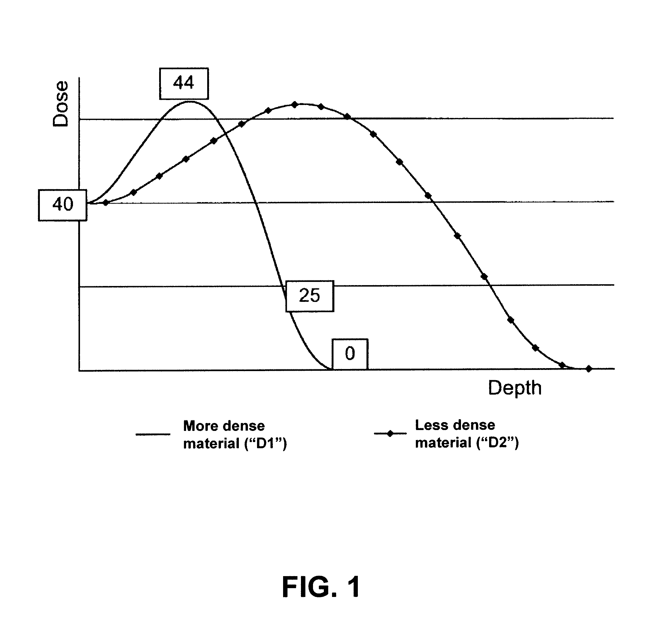
[0030]FIG. 1 depicts a depth dose distribution curve illustrating the relationship between radiation exposure and depth of penetration of a radiation beam for materials with two densities. The curve shows the dose versus the depth of a material that the electrons travel through for two different densities, a higher density D1 and lower density D2. As depicted, the dose initially rises, then drops off, in each case. When the material is more dense, e.g., D1, the ramp up is more rapid and the decline in dose level verses depth is more rapid. For example, if a device is characterized as having the density D1 is irradiated with 40 kGy, the peak dose is at 44 kGy, and eventually drops down to, for example, 25 kGy and finally to 0 kGy upon further permeation through a material. The sharp ramp-up near the front face of the material having the higher density may be explained, at least in part, by the increased frequency of collisions between the incoming electrons and the denser material ne...


PUM

PropertyMeasurementUnit
bio-absorbable aaaaaaaaaa
densityaaaaaaaaaa
bio-absorbableaaaaaaaaaa

Abstract

A system and method for sterilization of medical devices includes methods for reducing the variance in dose levels over the medical device by either varying the dose levels for each pass before a radiation source, such as an electron beam, or by increasing the number of passes before a radiation source.

Description

BACKGROUND OF THE INVENTION[0001]1. Field of the Invention[0002]The present invention relates to a medical device; more particularly, this invention relates to methods of sterilizing the medical device by irradiation of the medical device.[0003]2. Background of the Invention[0004]Systems for sterilizing products such as food or mail to remove harmful micro-organisms are known in the art. Such a system may operate as a conveyor in which products are carried pass a radiation source where the product is subjected to a predetermined dose of radiation, e.g., X-ray, gamma or electron radiation, at a predetermined level or intensity. Careful and continuous control of the dose delivered to a product is critical. If a product receives too little radiation, the desired sterilization, pasteurization, and / or chemical modification is not obtained. If a product receives too much radiation, the treatment is damaging to the product.[0005]It is known to expose a product to two passes before a radiat...

Claims


Application Information

Patent Timeline
Patent Type & Authority Applications(United States)
IPC IPC(8): A61L2/08
CPCA61L2/08A61L2/24A61L2/087
Inventor SIMMONS, GREGORY SCOTTRIGGS, BRIAN
Owner ABBOTT CARDIOVASCULAR
Why Eureka
Try Eureka