Apparatus and method for assessing percutaneous implant integrity

a technology for percutaneous implants and apparatus, applied in calibration apparatus, vibration detection, solids analysis using sonic/ultrasonic/infrasonic waves, etc., can solve problems such as poor image resolution in this vital area, failure of implants, and limited techniques in monitoring the actual bone-implant interfa

Inactive Publication Date: 2011-10-27
COVENANT HEALTH
View PDF2 Cites 18 Cited by
  • Summary
  • Abstract
  • Description
  • Claims
  • Application Information

AI Technical Summary

Benefits of technology

[0061]According to another broad aspect, there is provided an apparatus for determining a property of an interface between a medium and an implant that is at least partially embedded therein, the apparatus comprising: an input for receiving a signal generated from a motion of an impact body during impact with an abutment connected to the implant; and a property determiner for: (a) maintaining a mathematical model for impacting the impact body against the abutment; (b) determining a system property from the signal; and (c) analytically determining the property of the interface by applying the system pr...

Problems solved by technology

If this does not occur, the development of connective soft tissue in the bone-implant interface may begin and can lead to failure of the implant.
However, these techniques are limited in their ability to monitor the actual bone-implant interface, as the implant tends to shield this region resulting in poor image resolution in this vital area.
Therefore, the condition of the bone-implant interface including the implant threads and the adjacent tissue undergoing remodelling is much more difficult to evaluate.
Furthermore, images obtained in this manner are costly and high quality radiographs carry additional risks associated with radiation exposure....

Method used


Image

  • Apparatus and method for assessing percutaneous implant integrity
  • Apparatus and method for assessing percutaneous implant integrity
  • Apparatus and method for assessing percutaneous implant integrity

Examples


Embodiment Construction

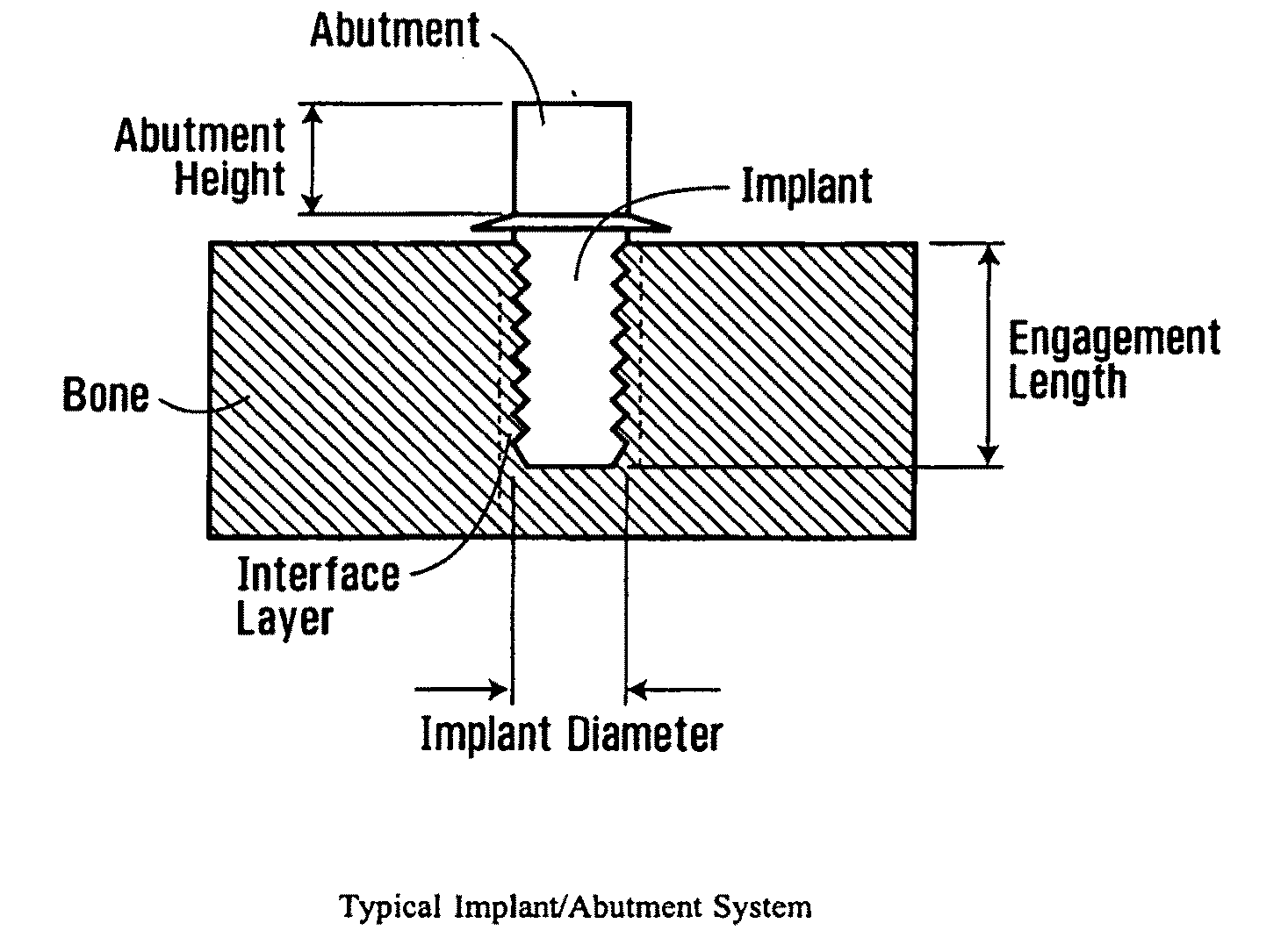
[0067]While the methods of the present invention are described in the context of an impact test conducted on an abutment attached to an artificial implant, it is to be understood that these methods may also be employed in the context of natural dentition. Thus, in this specification, the term “abutment” includes the crown of a natural tooth, while “implant” includes the root of a tooth. It is also to be understood that the present invention is applicable to replacement teeth. In such applications, the “implant” is synthetic and might for example be formed of titanium. The “abutment” connected to the implant is also synthetic and is typically designed to function as a tooth crown.

Section I: Zero Phase Shift Filter

Introduction

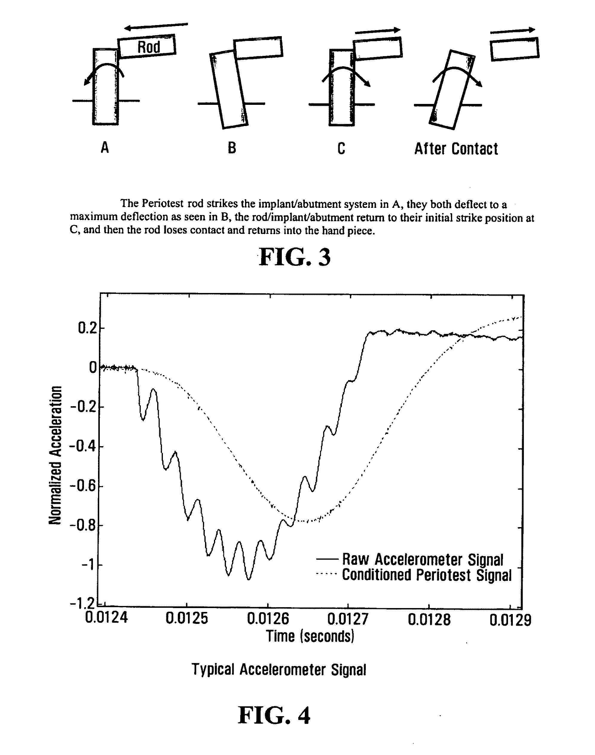
[0068]Referring now to FIG. 3, shown is a schematic drawing of a Periotest rod striking an implant abutment. At point A, the Periotest rod strikes the implant abutment. The Periotest rod and the implant abutment remain in contact through points B and C. At point ...


PUM


Abstract

Provided is an apparatus for assessing interface integrity between a medium and an implant. A first signal is translated from a motion of an impact body during impact with an abutment connected to the implant. In some embodiments, the first signal is filtered using a zero phase shift filter and then used for assessing the interface integrity. Since no phase shift is introduced, the interface integrity is accurately assessed. In another embodiment, the apparatus maintains a system model for impacting the impact body against the abutment. The apparatus analytically determines an interface property by applying a system property that has been determined to the system model. An accurate system model allows for an accurate assessment. According to another broad aspect, there is provided a method of conducting the impact test. According to the method, a person ensures that the impact body impacts against a consistent portion of the abutment.

Description

FIELD OF THE INVENTION[0001]This invention relates to techniques for assessing percutaneous implant integrity, and in particular to careful control of conditions under which impact-style techniques are utilised, and the analysis of data received therefrom.BACKGROUND OF THE INVENTION[0002]Osseointegrated implants are routinely utilized in a broad range of oral and extraoral applications including removable and fixed dental prostheses, in re-construction of the head and neck, as a transmission path for bone anchored hearing aids (BAHA™), to provide anchorage in orthodontic treatment and in orthopedic applications. FIG. 1 shows a cross-sectional side view of a typical in-situ implant and abutment system. Such implants are typically 3-6 mm in diameter and range in length from 3-4 mm (BAHA and orbit applications) to 7-20 mm (dental reconstructions). Such implants are often formed of Titanium.[0003]The success of these implants is dependent on the quality of the bone-implant bond at the i...

Claims


Application Information

Patent Timeline
IPC IPC(8): G01D18/00G01D21/00
CPCA61B5/0048A61B5/11A61B5/4504A61B9/00A61C19/04A61B5/682A61C8/00A61B5/0051G01N29/045G01N29/4418G01N29/4472G01N2291/0258G01N29/12
Inventor FAULKNER, GARYRABOUD, DONALD WAYNESWAIN, RYAN CLAIRWOLFAARDT, JOHAN FRANCIS
Owner COVENANT HEALTH
Why Eureka
Try Eureka