
Light-Emitting Device

a light-emitting device and light-emitting technology, which is applied in the direction of solid-state devices, electric lighting sources, and light-emitting properties of organic el elements, can solve the problems of low transmittance to visible light rays, disadvantages that are noticeable in short wavelengths, and light-emitting devices that cannot show the color of light-emitting with good color rendering properties, etc., to achieve low emission characteristics, short life, and high efficiency

Inactive Publication Date: 2011-10-27
SEMICON ENERGY LAB CO LTD
View PDF3 Cites 8 Cited by
  • Summary
  • Abstract
  • Description
  • Claims
  • Application Information

AI Technical Summary

Benefits of technology

[0014]In view of the above problem, an object of the present invention is to provide a light-emitting device using an organic EL element which has high efficiency and the capability of modulating light emission colors.
[0019]The light emission from the light-emitting diode preferably has a longer wavelength than the light emission from the organic EL element to suppress attenuation of a larger amount of light.
[0022]The light-emitting device including an organic EL element according to one embodiment of the present invention has very high efficiency even with the capability of modulating light emission colors. The present invention is effective particularly in a light-emitting device including an organic EL element that emits blue light. Since an organic EL element that emits short-wavelength light has a short lifetime and low emission characteristics as described above, according to one embodiment of the present invention in which attenuation of blue light can be suppressed in a light-emitting device formed to emit light at a plurality of wavelengths, a light-emitting device having a high luminance, a long lifetime, and the capability of modulating light emission colors can be provided. Further, the light-emitting device has a function of separately controlling voltages applied to the organic EL elements to suppress a change in color tone. This feature is particularly effective in a backlight of a liquid crystal panel for which color reproducibility is important, a lighting device for home use, and the like. Furthermore, use of a self-luminous light-emitting element having a light-transmitting property eliminates the need to form a three-dimensional module such as a dichroic mirror used for a three-plate type full color liquid crystal projector, and a board-like structure enables a mixture of colors as in such a projector, according to one embodiment of the present invention.

Problems solved by technology

An electrode having a light-transmitting property used for an organic EL element has a disadvantage of a low transmittance to visible light rays.
This disadvantage becomes noticeable particularly for short wavelengths, i.e. blue to purple.
However, without the blue color, a light-emitting device cannot show the color of light emission with good color rendering properties.
Therefore, how to manufacture a light-emitting device without attenuation of blue light has been a big challenge.

Method used


Image

  • Light-Emitting Device
  • Light-Emitting Device
  • Light-Emitting Device

Examples


embodiment 1

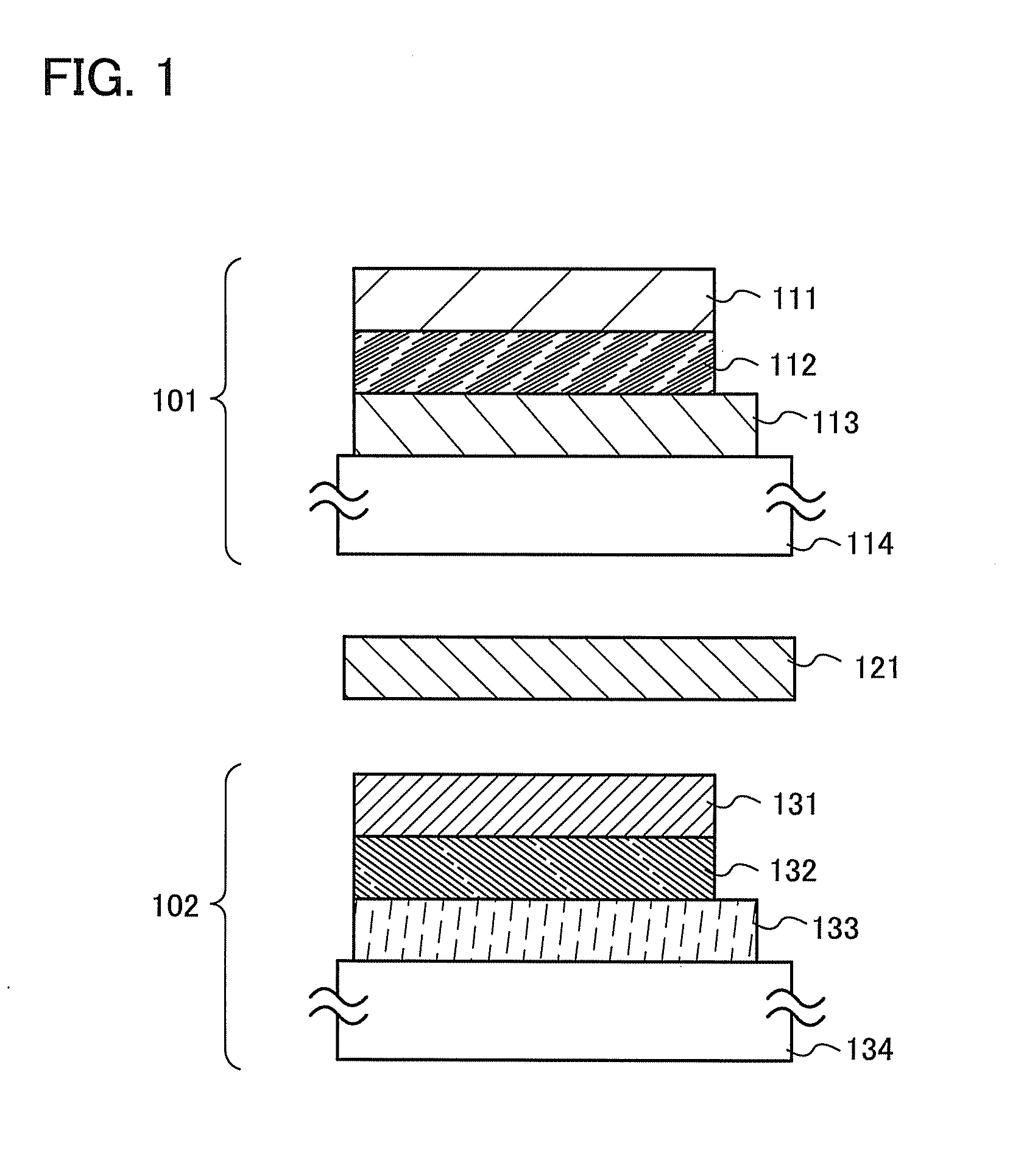
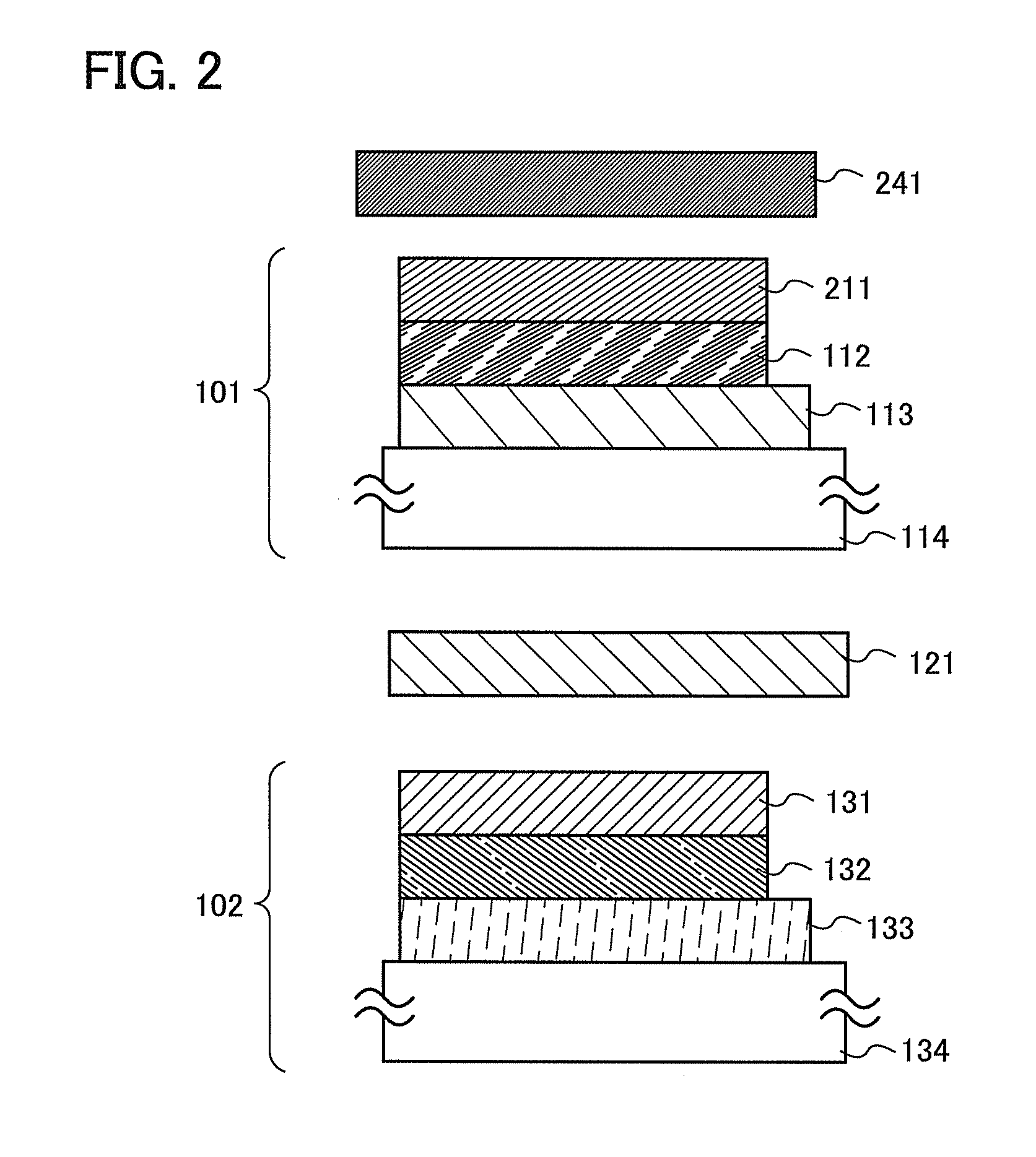
[0031]A light-emitting device according to one embodiment of the present invention will be described with reference mainly to FIG. 1. FIG. 1 is a cross-sectional view illustrating a basic structure of the light-emitting device. FIG. 2 illustrates an example in which the light-emitting device is partly modified. In this specification, an organic EL element refers to a component that has an organic EL layer serving as a light-emitting region between a pair of electrodes and emits light by application of a voltage between the electrodes. In addition, a light-emitting device refers to a component that emits mixed color light using at least one such organic EL element.

[0032]In FIG. 1, a first organic EL element 101 includes a reflective electrode 111, an electrode 113 having a property of transmitting visible light rays, and an organic EL layer 112 therebetween. Further, a second organic EL element 102 includes a pair of electrodes 131 and 133 having a property of transmitting visible li...

embodiment 2

[0042]A light-emitting device according to one embodiment of the present invention will be described using FIG. 3. FIG. 3 is a cross-sectional view illustrating a basic structure of the light-emitting device including a light-emitting diode and an organic EL element.

[0043]In the light-emitting device illustrated in FIG. 3, the first organic EL element 101 illustrated in FIG. 1 is replaced with a light-emitting diode 301. Since the light-emitting diode has a long lifetime which might exceed 100,000 hours, it can provide a light-emitting device having a longer lifetime by being used in combination with the organic EL element. Since the light-emitting diode is nearly a point light source unlike the organic EL element, light with a higher luminance can be obtained by arrangement of light-emitting diodes in a matrix.

[0044]Light emission from the light-emitting diodes arranged in a matrix is not limited to having a single color, and can have a variety of colors. The light emission from th...

embodiment 3

[0046]In this embodiment, a method of forming an organic EL element applicable to one embodiment of present invention will be described.

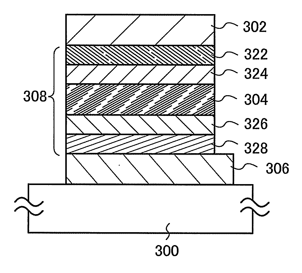
[0047]For example, organic EL elements illustrated in FIGS. 4A and 4B can be fabricated. In the organic EL element illustrated in FIG. 4A, a first electrode layer 302, an EL layer 308 which serves as a light-emitting layer 304, and a second electrode layer 306 are sequentially stacked over a substrate 300. One of the first electrode layer 302 and the second electrode layer 306 functions as an anode, and the other functions as a cathode. Holes injected from the anode and electrons injected from the cathode recombine in the light-emitting layer 304, whereby light emission can be obtained. In this embodiment, the first electrode layer 302 functions as an anode and the second electrode layer 306 functions as a cathode.

[0048]In the organic EL element illustrated in FIG. 4B, a hole-injection layer, a hole-transport layer, an electron-transport layer, and ...


PUM


Abstract

Blue organic EL elements, which have a shorter lifetime and lower luminance characteristics than green and red ones, have had a problem: particularly when blue elements are used in a light-emitting device capable of modulating light emission colors, light significantly attenuates and characteristics further deteriorates. A dielectric mirror which is selective in wavelength is provided between organic EL elements, and the number of times especially blue light emission from an organic EL element is transmitted through an electrode having a light-transmitting property is reduced as much as possible, so that attenuation of light is suppressed. Thus, a light-emitting device capable of modulation of light emission colors which has a high luminance and a long lifetime can be provided. In the light-emitting device, voltages applied to the organic EL elements, which deteriorate individually, are separately controlled, whereby the color tone can be kept constant for a long period.

Description

BACKGROUND OF THE INVENTION[0001]1. Field of the Invention[0002]The present invention relates to a light-emitting device using a light-emitting element that emits phosphorescence or fluorescence. A disclosed embodiment of the present invention relates to a light-emitting device in which light-emitting elements that emits light having different colors are combined. Note that the term light-emitting device encompasses an image display device, a light-emitting device, and a light source (including a lighting device).[0003]2. Description of the Related Art[0004]In recent years, light-emitting devices which have electroluminescence (hereinafter, referred to as EL) elements using EL as self-luminous light-emitting elements have been actively researched. The light-emitting devices are used for organic EL display devices, organic EL lighting devices, and the like. Such light-emitting devices are also called organic light-emitting diodes. The light-emitting devices provided with EL elements ...

Claims


Application Information

Patent Timeline
Patent Type & Authority Applications(United States)
IPC IPC(8): H01L33/46
CPCH01L25/048H05B33/22H01L27/3225H01L27/3209H01L2924/0002H10K59/90H10K59/32H10K59/80518H10K59/878H01L2924/00H10K59/00
Inventor AOYAMA, TOMOYASEO, SATOSHI
Owner SEMICON ENERGY LAB CO LTD
Learn More