Polarization coupler

a polarization coupler and laser technology, applied in the direction of laser optical resonator construction, lasers, instruments, etc., can solve the problems of deterioration of others, power densities which would destroy components, and output power or power density still too low for many exciting applications, so as to reduce the efficiency of lasing lines, reduce the efficiency of coupling, and reduce the effect of power density

Inactive Publication Date: 2011-10-27
RAAB VOLKER
View PDF0 Cites 25 Cited by
  • Summary
  • Abstract
  • Description
  • Claims
  • Application Information

AI Technical Summary

Benefits of technology

With conventional polarization coupling it is only possible to superimpose two beams which results in an unpolarized combined beam. Here it becomes possible to re-establish linear polarization. This becomes feasible by active feedback or predefinition of different wavelengths. The invention describes how the light of different beam sources becomes aligned parallel (“rectified”) along a common path along the optical propagation. If need should be this process of rectified polarization coupling can be repeated with the resulting beams. This cascades the number of combined beams in powers of two. As a result much higher total output powers become possible without forfeit in beam diameter, divergence or polarization.
As opposed to known procedures to spectrally multiplex beams by means of gratings or low bandwidth dichroic filters the coupling efficiency is much higher and the spectral distance of wavelengths can be much smaller for same footprints as will be elaborated below.
The damage thresholds of birefringent crystals like calcite or BBO is extraordinarily high and exceeds that of gratings by many orders of magnitude.
Additionally the angle between neighboring beams can be very large due to the orthogonal polarization. For the case of a common polarization beam splitter cube it is 90°. Therefore the different gain regions can be almost freely positioned. For an exemplary system which consists of a calcite crystal of a thickness of 1 cm and which operates around a central wavelength of 650 nm the spectral distance between two wavelengths is about 0.08 nm or an odd multiple of that. Even though the filter itself has a size of only a few cm3 it can easily separate the two beams by a few cm. To achieve a spatial separation of only 1 cm for the same wavelength separation of 0.08 nm with a grating of 3000 lines/mm a propagation dis...

Problems solved by technology

Improvements of one chosen parameter thus tend to lead to deterioration of others.
Currently, the output power or the power density achievable is still too low for many exciting applications.
This is because the light is generated in volumes that are significantly smaller than 1 mm3, and therefore lead to power densities which would destroy the component when increased further.
Increasing the volume is no solution because then the modal selectivity decreases and as a result the beam quality deteriorates whi...

Method used


Image

  • Polarization coupler
  • Polarization coupler
  • Polarization coupler

Examples


Embodiment Construction

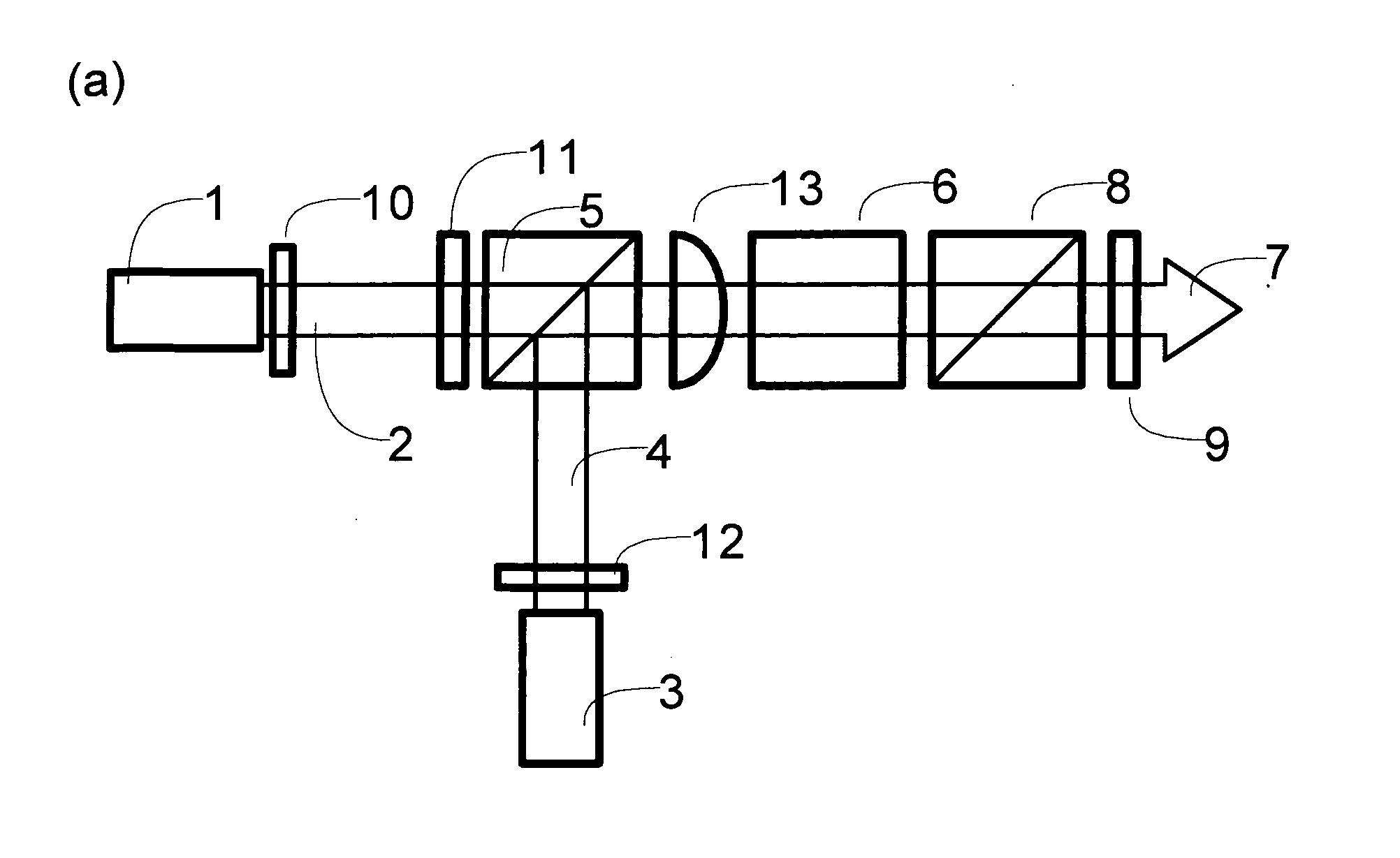
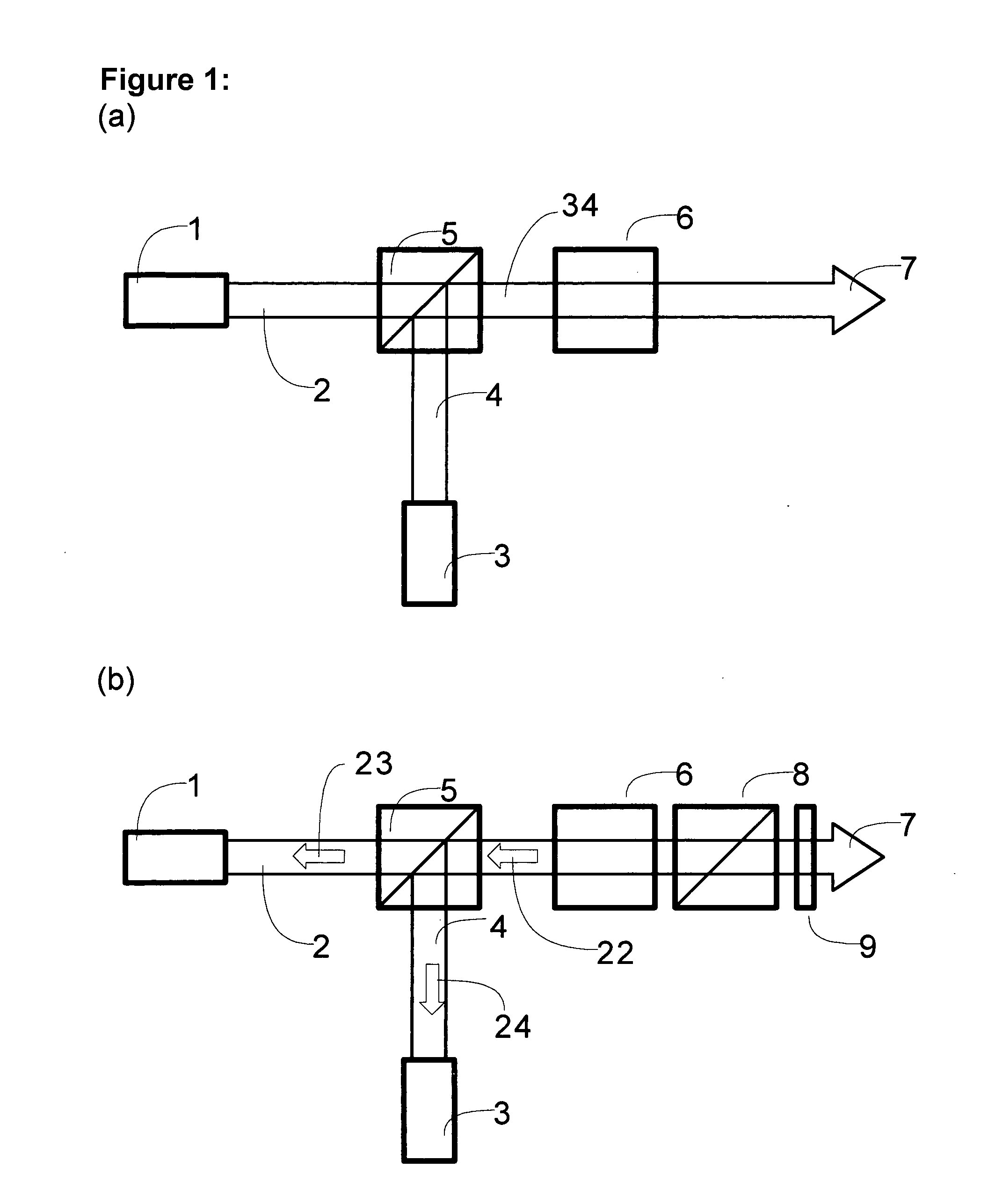
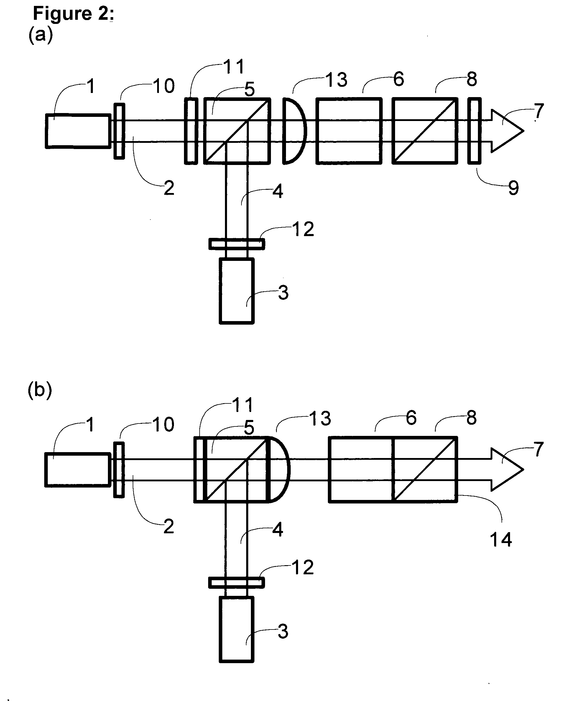
A principal depiction of the assembly is shown in FIG. 1 in sub-figure (a). According to this Figure two beam sources (1) and (3) each emit light (2) and (4) respectively having different wavelengths. This light is preferably orthogonal polarized. The two beams are superimposed by a polarizing beam splitter (5) into a common beam (34). This beam incidents onto a birefringent crystal (6). The birefringence is dispersive which means dependent on wavelength. The optical axis of the birefringent crystal shall be aligned under an inclination of 45° with respect to the polarization of the two beams. This alignment is preferable for retarders and quite common because then the dispersively birefringent crystal acts as a wave plate and directly influences the orientation of polarization of both beam sources. Thanks to the dispersion it is possible to choose such a thickness of the crystal that it acts as a half-wave plate for one wavelength and phase-neutral for the other. Concretely the pha...


PUM


Abstract

The invention comprises an assembly (a) by which two polarized beam sources (1) and (2) of different wavelength by means of polarizing beam splitters (5) can be superimposed. By means of a dispersively birefringent crystal (6) both beams are rectified to reconstitute the linear polarization.
If, as assumed in (b), the beam sources can react spectrally to feedback, an additional polarization filter (8) and a partially reflecting coating (9) can ensure that suitable wavelengths are established automatically.
This assembly can be scaled as depicted in (b). By help of further dispersively birefringent crystals (6) and birefringent displacers more beams can be combined into a single beam, eight sources in the given setup.

Description

TECHNICAL FIELD OF APPLICATIONThe invention aims at increasing the power density of lasers and particularly semiconductor lasers by means of a new method of polarization coupling by which beams of different wavelengths are being superimposed.BACKGROUND AND PRIOR ARTEach laser consists of a laser active region, also called gain region, in which the supplied energy is converted by stimulated emission into coherent radiation. For this purpose a laser resonator is needed to ensure that a part of the emerging radiation is passed back into the gain region. Therefore, it contains at least one feedback element, typically a semitransparent mirror. This resonator determines—by its geometry and physical properties—the feedback characteristics of the laser light, in particular the spatial profile, the wavelength, bandwidth, and polarization. The estimated achievable characteristics depend on the gain material and the resonators and are usually inversely correlated with each other and the achiev...

Claims


Application Information

Patent Timeline
IPC IPC(8): G02B5/30
CPCG02B27/283H01S3/07H01S3/08054H01S3/08059H01S3/08086H01S5/4062H01S3/082H01S5/14H01S5/141H01S5/4006H01S5/4012H01S3/0813
Inventor RAAB, VOLKER
Owner RAAB VOLKER
Why Eureka
Try Eureka