Ophthalmological laser system and operating method

a laser system and laser technology, applied in the field of ophthalmological laser systems, can solve the problems of low intensity of light backscattered in the eye lens, relatively large number of detection flaws, etc., and achieve the effect of high accuracy, great accuracy and great accuracy

Active Publication Date: 2011-10-27
CARL ZEISS MEDITEC AG
View PDF15 Cites 42 Cited by
  • Summary
  • Abstract
  • Description
  • Claims
  • Application Information

AI Technical Summary

Benefits of technology

[0023]Contrary to refractive surgery on the cornea, it is impossible to immobilize the eye lens. Only the eye as a whole can be immobilized. The operating method, according to the invention, solves said problem, whereby, at first, the eye as a whole is immobilized and the actual form / structure / position of the lens is subsequently determined. Since the therapy step follows immediately thereafter and both steps can be completed in a short period of time, form / structure / position of the lens for determining the irradiation control data are immediately applied in the therapy step, rendering an immobilization of the lens unnecessary. However, for the therapy, a very high accuracy is nevertheless possible.
[0024]In other example embodiments of the laser system, a lock-in amplifier, coupled with the laser, is provided for the detector. This allows for the mapping of the detector signals with great accuracy, so that a possible therapy can also be executed with great accuracy.
[0025]In another example embodiment, the scanning process is effected in such a way that two consecutive scan points differ from each other in all three spatial coordinates. Through this type of scanning, a representative model of the eye lens with regard to form / structure / position can be obtained in a short period of time. This allows for decreasing the inaccuracy caused by movements of the lens by the patient. A control of the scanners in the form of a sine function is technically particularly advantageous. Controlling the x-y scanners in such a way that one of the scanners is controlled with exactly double the frequency than that of the other scanner results in a Lissajous figure, which resembles the FIG. 8.
[0026]A pulse frequency of the laser light, depending on the motion speed of a focal point of the laser beam relative to the eye lens, may be chosen. As a result, the radiation exposure of the lens and the eye overall can be decreased during analysis and / or particularly during therapy.

Problems solved by technology

A problem is that the intensity of the light backscattered in the eye lens is very low due to the inherent properties of the eye lens—for a high imaging quality, the scatter must be as slight as possible.
As a result, the detection contains a relatively great number of flaws.

Method used


Image

  • Ophthalmological laser system and operating method
  • Ophthalmological laser system and operating method
  • Ophthalmological laser system and operating method

Examples


Embodiment Construction

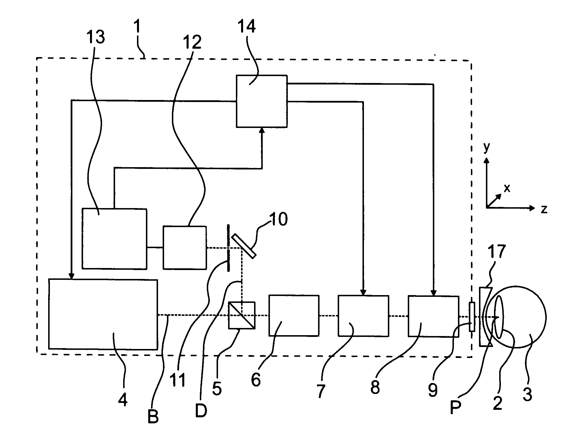
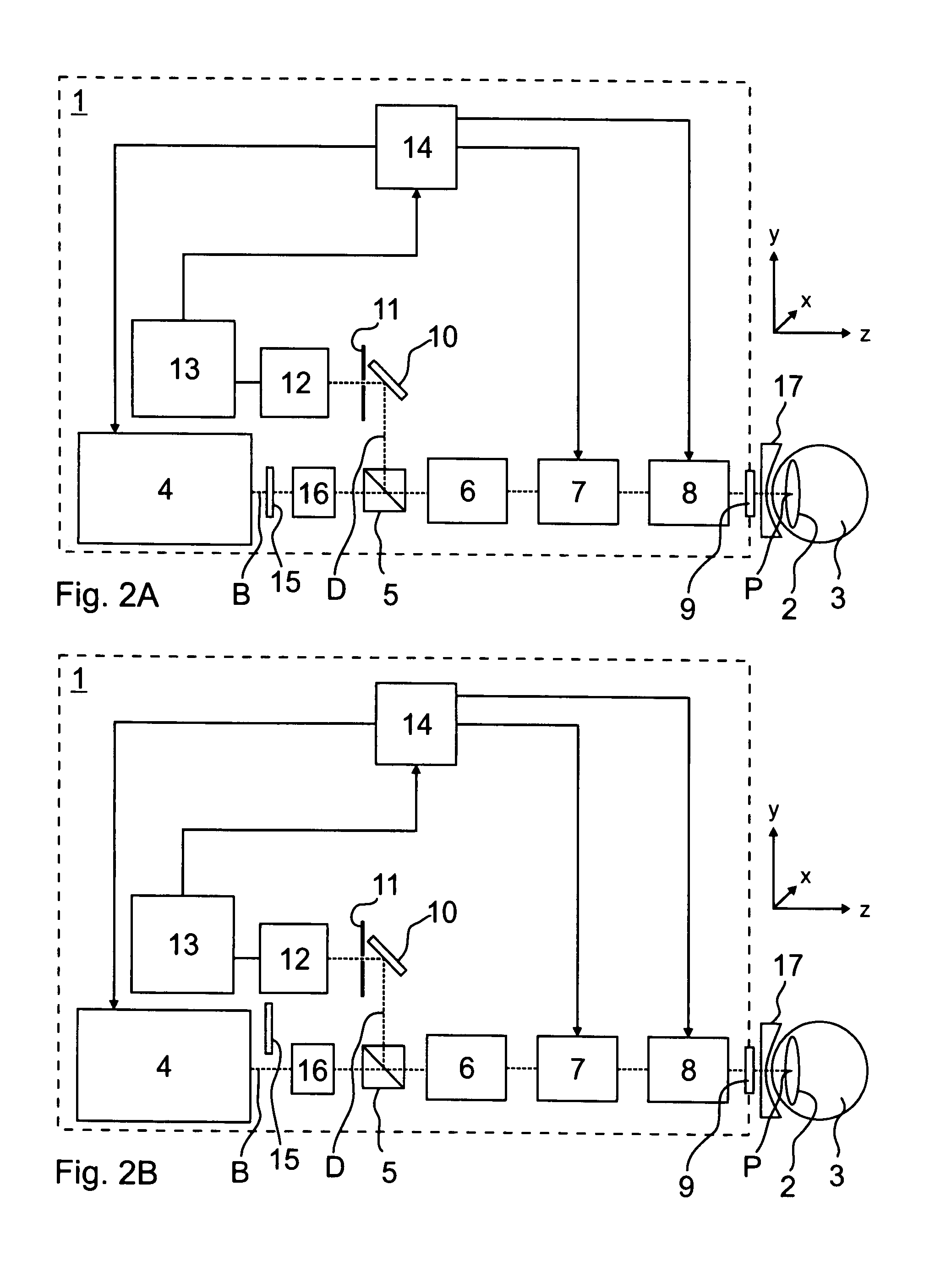
[0035]FIG. 1 shows an exemplary ophthalmological laser system 1 for the analysis of a presbyopia of an eye lens 2 of an eye 3. The laser system 1 comprises a laser 4, a polarization beam splitter 5, scan optics 6, a scanner unit 7, focusing optics 8, and an optical phase retardation system 9, which together form an illumination beam path B; as well as a deflection mirror 10, a confocal aperture diaphragm 11, and a detector 12, which form a decoupled detection beam path D; and an amplifier 13 and a control unit 14.

[0036]Between the laser system 1 and the eye 3, a contact glass 17 with an immobilization device for the eye 3 is positioned, behind which lies the examination region. Other embodiments for the realization of the solution, according to the invention, are possible (not depicted).

[0037]For example, the laser 4 is designed as pulsed TiSa infrared laser with a pulse length between 100 fs and 1000 fs. It emits laser radiation at an eye-safe illumination laser power in the range ...


PUM


Abstract

A polarization beam splitter selectively decouples detection light onto a detector such that it has a polarization direction that differs from the emitted illumination light. This enables the detection of the light scattered back in the eye lens at a high level of accuracy, since stray light from reflections at optical components of the light path is suppressed. In the generating of photo disruptions or other incisions, the ray exposure of the retina may be reduced in that the incisions being furthest away from the laser are induced first such that laminar gas inclusions with an existence duration time of at least 5 seconds result. In this manner the laser radiation propagated in the direction of the retina in further incisions are scattered and partially reflected such that the influence impinging upon the retina is reduced.

Description

PRIORITY CLAIM[0001]The present application is a National Phase entry of PCT Application No. PCT / EP2009 / 003980, filed Jun. 4, 2009, which claims priority from German Application Number 102008027358.9, filed Jun. 5, 2008, the disclosures of which are hereby incorporated by reference herein in their entirety.FIELD OF THE INVENTION[0002]The invention relates to an ophthalmological laser system, particularly for analysis and / or therapy of a presbyopia, with a laser, the radiation of which is focusable in an examination region as illumination light via an illumination beam path, which exhibits a beam splitter, a scanner unit, and focusing optics, whereby radiation, which reaches the beam splitter from the direction of the examination region, reaches a detector as detection light through a confocal aperture diaphragm. Furthermore, the invention relates to an operating method for an ophthalmological laser system.BACKGROUND[0003]Accommodation is the ability of the eye to create a sharp imag...

Claims


Application Information

Patent Timeline
Patent Type & Authority Applications(United States)
IPC IPC(8): A61F9/008A61B3/10
CPCA61B3/1173A61F2009/0087A61F9/00838A61F9/008
Inventor REICH, MATTHIASGREBNER, DIETERKOCH, ANDREASLEDERMANN, JUERGENDICK, MANFREDHANFT, MARCO
Owner CARL ZEISS MEDITEC AG
Why Eureka
Try Eureka