Packaged thermoelectric conversion module

a thermoelectric conversion module and thermoelectric conversion technology, applied in the direction of thermoelectric devices with peltier/seeback effect, basic electric elements, electric apparatus, etc., can solve the problems of difficult to increase difficult to realize the size of the thermoelectric conversion module having a larger than that described above, and difficulty in increasing the size of the thermoelectric conversion module, etc., to achieve the effect of reducing the thermal contact resistance at the contact interface, reducing the thermal contact resistance resistan

Inactive Publication Date: 2011-11-03
CENTRAL RESEARCH INSTITUTE OF ELECTRIC POWER INDUSTRY
View PDF0 Cites 27 Cited by
  • Summary
  • Abstract
  • Description
  • Claims
  • Application Information

AI Technical Summary

Benefits of technology

[0015]According to the packaged thermoelectric conversion module of the present invention, the contact interface of both surfaces of the thermoelectric conversion module are satisfactorily in intimate contact clue to pressing force caused by the differential pressure between the inside and the outside of the airtight container, whereby the thermal contact resistance at the contact interface can be reduced. Specifically, the thermoelectric conversion module in the case and the partition plate serving as the cooling or heating panel and the upper case serving as the heating or cooling panel are pressed against each other by the differential pressure between the inside and the outside of the case, whereby the thermal contact resistance can be reduced, and a large temperature difference can be applied to the thermoelectric semiconductor.
[0016]One thermal medium for applying the temperature difference to the thermoelectric conversion module circulates in the airtight container, whereby the heat of the thermal medium can stably be applied to the thermoelectric conversion module. Therefore, one of the surfaces of the thermoelectric semiconductor is heated or cooled by a radiation heat transfer from a radiant heat source opposite to the packaged thermoelectric conversion module or convection heat transfer by the thermal medium flowing around the packaged thermoelectric conversion module, and the other surface of the thermoelectric semiconductor is cooled or heated by the cooling fluid or the heating fluid flowing through the flow path in the airtight container via the partition plate, whereby the mechanism for pressed contact or an application of a viscous thermal-conductive material such as a thermal-conductive grease between the airtight container and the duct introducing the thermal medium are not required. Even when a duct for flowing a heating fluid or a cooling fluid is in pressed contact with one surface of the thermoelectric semiconductor, i.e., one surface of the airtight container, so as to transfer or receive heat, the duct is only pressed against one surface of the airtight container of the packaged thermoelectric conversion module, with the result that the pressing mechanism can be simplified. Accordingly, restriction is not imposed on the usage of the packaged thermoelectric conversion module according to the present invention. Therefore, the packaged thermoelectric conversion module can be used only by arranging the same under any environment, such as under the radiation heat from a high-temperature heat source, for example, under the environment in which waste heat radiated from a heated component generated in an industrial furnace such as a powdered metallic ceramic sintering furnace or various electric furnaces is used as a heat source of a radiation heat transfer, under the environment in which waste gas or high-temperature fluid such as waste liquid discharged from various industrial facilities involved with heat, such as an industrial waste sintering furnace is used as a heat source of convection heat transfer, or under the environment in which heat obtained with a thermal conduction through a contact to a solid heat source is used as a heat source.
[0017]In the packaged thermoelectric conversion module according to the present invention, the components of the thermoelectric conversion module are sealed in the airtight container. Therefore, the deterioration of the components, contained in the container, of the thermoelectric conversion module due to the oxidation can be prevented without being affected by ambient air. Further, since the components of the thermoelectric conversion module are contained in the airtight container, external physical shock or a rapid change in an external atmosphere such as external pressure or temperature are eased, and the strength to the external force is increased.
[0018]When the surface of the airtight container that is in contact with at least the other surface of the thermoelectric semiconductor, i.e., with the surface of the thermoelectric semiconductor opposite to the chamber for circulating the thermal medium, is made of a thermal-conductive material having flexibility, the surface opposite to the thermoelectric conversion module is deformed due to the differential pressure between the inside and the outside of the container, and is pressed against the thermoelectric conversion module to be in intimate contact therewith, whereby the heat resistance can be reduced.
[0019]When the airtight container includes the upper case and the lower case, wherein the thermal medium circulating chamber is formed by a gate provided at the bottom part of the lower case, while the partition plate is fitted to be bonded to a striker plate formed on the top surface of the gate enclosing the thermal medium circulating chamber so as to form a liquid-tight flow path between the partition plate and the lower case, the thermal medium flows in the airtight container without leakage, whereby one surface of the thermoelectric conversion module is cooled or heated.
[0020]When the flow path is configured by a single heavily winding groove in order to allow the thermal medium to flow therein, the thermal medium uniformly flows, whereby the heat can efficiently be applied to one surface of the thermoelectric conversion module.

Problems solved by technology

However, this structure makes it difficult to increase the size of the thermoelectric conversion module.
A thermoelectric conversion module having a size larger than that described above is difficult to be realized, because shearing force caused by a thermal expansion of a heating plate sandwiching the thermoelectric semiconductor might break a fragile thermoelectric semiconductor, or the respective members might be peeled on the bonding surface.
This problem is particularly significant in a high-temperature thermoelectric conversion module having an operating temperature of 500° C. or higher, which module is supposed to use a waste heat from industrial facilities involved with heat, such as a vehicle or an industrial furnace, as a heat source.
However, another problem involves with the increase in size as described above, so that increasing size is difficult.
However, when the thermoelectric semiconductor is strongly sandwiched between a heating plate and a cooling plate for attaining an intimate contact between the respective components of the thermoelectric module, the weak thermoelectric semiconductor might be crushed.
Therefore, it is difficult to reduce heat resistance.
When a thermoelectric conversion module is placed in an oxidation atmosphere such as in high-temperature air, or in a corrosive atmosphere such as in combustion gas in a garbage incinerator, a thermoelectric conversion module having a thermoelectric semiconductor or an electrode portion exposed to ambient air might be oxidized or might be corrosive.
However, the system described above not only needs a structure such as a duct or a partition wall, but also has a drawback of deteriorating power-generating property of the thermoelectric conversion module by an amount corresponding to the reduction in the difference in the temperature applied to the thermoelectric semiconductor due to the indirect heating.

Method used


Image

  • Packaged thermoelectric conversion module
  • Packaged thermoelectric conversion module
  • Packaged thermoelectric conversion module

Examples


example

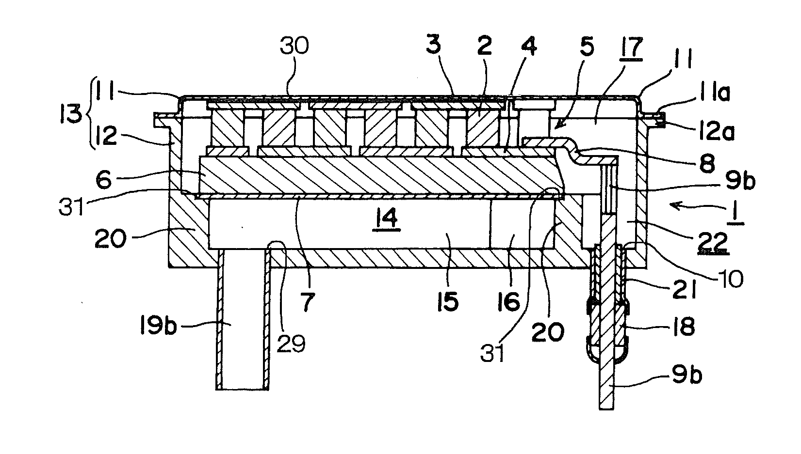
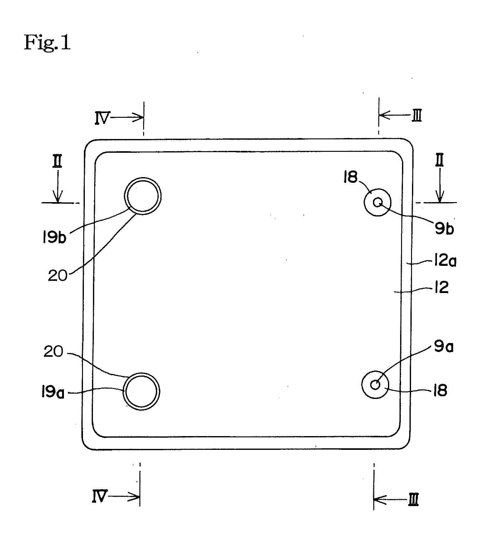
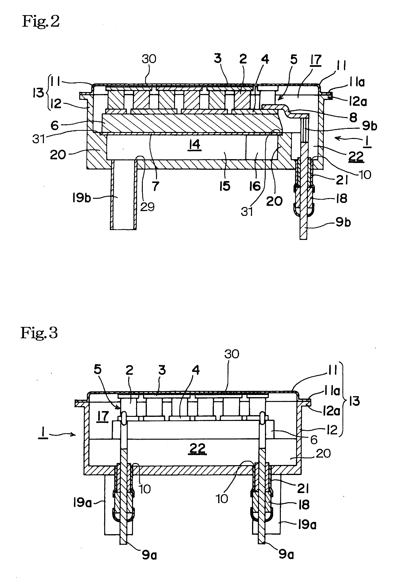
[0054]The performance of the packaged thermoelectric conversion module according to the present invention was compared to that of an exposed thermoelectric conversion module which was not contained in the airtight container as illustrated in FIG. 13. The components of the packaged thermoelectric conversion module and the thermoelectric conversion module are identified by the same numerals, and the detailed description will be skipped.

[0055]Firstly, a low-temperature thermoelectric conversion modules 5 was prepared by using BiTe of 4×4 mm as the thermoelectric semiconductor 2. The output was measured when a temperature of 150° C. was applied to the high-temperature side of the module, a temperature of 20° C. was applied to the low-temperature side, and a temperature difference of 130 K was applied. FIG. 14 illustrates the result. It was confirmed from the result that the output of 3.2 W was obtained.

[0056]Next, the thermoelectric conversion modules having the configuration illustrate...


PUM


Abstract

A packaged thermoelectric conversion module that does not need a pressing mechanism for reducing a thermal contact resistance or an application of a thermal-conductive grease between a heat source of a thermoelectric conversion module sealed in an airtight container, wherein an interior of an airtight container 13 containing a thermoelectric conversion module 5 is decompressed or evacuated, wherein the interior of the airtight container 13 is partitioned into two chambers 14 and 17 by a partition plate 7, wherein one chamber 17 is provided with the thermoelectric conversion module 5 and electrodes 9a and 9b led out to the outside of the airtight container 13, while the other chamber 14 is provided with a flow path 16 for introducing a thermal medium 26 or 25 from an external thermal medium supplying source and circulating the thermal medium 26 or 25 between the chamber 14 and the external thermal medium supply source, and heat is transferred to or received from one surface of the thermoelectric semiconductor 2 by the thermal medium 26 or 25 via the partition plate 7, while heat is transferred or received between the other surface of the thermoelectric semiconductor 2 and an external heat source via the airtight container 13.

Description

TECHNICAL FIELD[0001]The present invention relates to a thermoelectric conversion module that generates electricity by utilizing a difference of a temperature applied to a thermoelectric semiconductor. More specifically, the present invention relates to an improvement of a packaged thermoelectric conversion module contained in an airtight container in order to realize a large-sized thermoelectric conversion module.BACKGROUND ART[0002]In a thermoelectric conversion module having a general structure of a conventional mass-production scale, electrodes are arranged on upper and lower surfaces of plural pairs of thermoelectric semiconductors so as to form an electric circuit, wherein a plate having electrically insulating property, such as a ceramic plate or a metallic plate having an electrical insulating film, is arranged at the outside of the respective electrodes so as to sandwich the electrodes, and they are bonded with a bonding member such as a bonding agent or brazing filler meta...

Claims


Application Information

Patent Timeline
Patent Type & Authority Applications(United States)
IPC IPC(8): H01L35/30
CPCH01L35/30H10N10/13
Inventor KAMBE, MITSURU
Owner CENTRAL RESEARCH INSTITUTE OF ELECTRIC POWER INDUSTRY
Why Eureka
Try Eureka