Electric device mounted in electric compressor

a technology of electric compressor and connection portion, which is applied in the direction of positive displacement liquid engine, liquid fuel engine, piston pump, etc., can solve the problems of restricting the connection portion between the external coupling terminal and the external coupling terminal from being conductive with the cooling medium, and achieves improved cooling performance of the circuit board, and improved reliability of the connection portion between the circuit board and the external coupling terminal

Inactive Publication Date: 2011-11-03
DENSO CORP
View PDF3 Cites 15 Cited by
  • Summary
  • Abstract
  • Description
  • Claims
  • Application Information

AI Technical Summary

Benefits of technology

[0013]In view of the above-described problem, it is an object of the present disclosure to provide an electric device, and cooling performance of a circuit board is improved, and reliability of an external coupling terminal and a connection portion between the circuit board and the external coupling terminal is improved.
[0015]Thus, since the circuit board is arranged in the cooling medium, the circuit board directly contacts the cooling medium. Accordingly, the cooling performance of the circuit board is improved. Further, since the device includes the separation member for separating the external coupling terminal and the connection portion between the external coupling electrode and the external coupling terminal away from the cooling medium, the external coupling terminal and the connection portion between the circuit board and the external coupling terminal are restricted from contacting the cooling medium. Thus, even when the cooling medium having corrosion action with respect to metal is used, the external coupling terminal and the connection portion between the circuit board and the external coupling terminal are restricted from corroding. Further, even when the cooling medium having conductivity is used, the external coupling terminal and the connection portion between the circuit board and the external coupling terminal are restricted from being conductive with the cooling medium. Accordingly, the cooling performance of the circuit board is improved, and the reliability of the external coupling terminal and the connection portion between the circuit board and the external coupling terminal are improved. Specifically, not only the cooling medium having non-conductivity but also the cooling medium having corrosion action with respect to metal or the cooling medium having conductivity can be used. Thus, a degree of freedom for selecting the cooling medium is improved. Here, since the electric element is mounted on the circuit board under a condition that the electric element is sealed, the reliability of the electric element is not reduced by the cooling medium even when the cooling medium having the corrosion action with respect to metal or the cooling medium having conductivity is used.

Problems solved by technology

Further, even when the cooling medium having conductivity is used, the external coupling terminal and the connection portion between the circuit board and the external coupling terminal are restricted from being conductive with the cooling medium.

Method used


Image

  • Electric device mounted in electric compressor
  • Electric device mounted in electric compressor
  • Electric device mounted in electric compressor

Examples


first embodiment

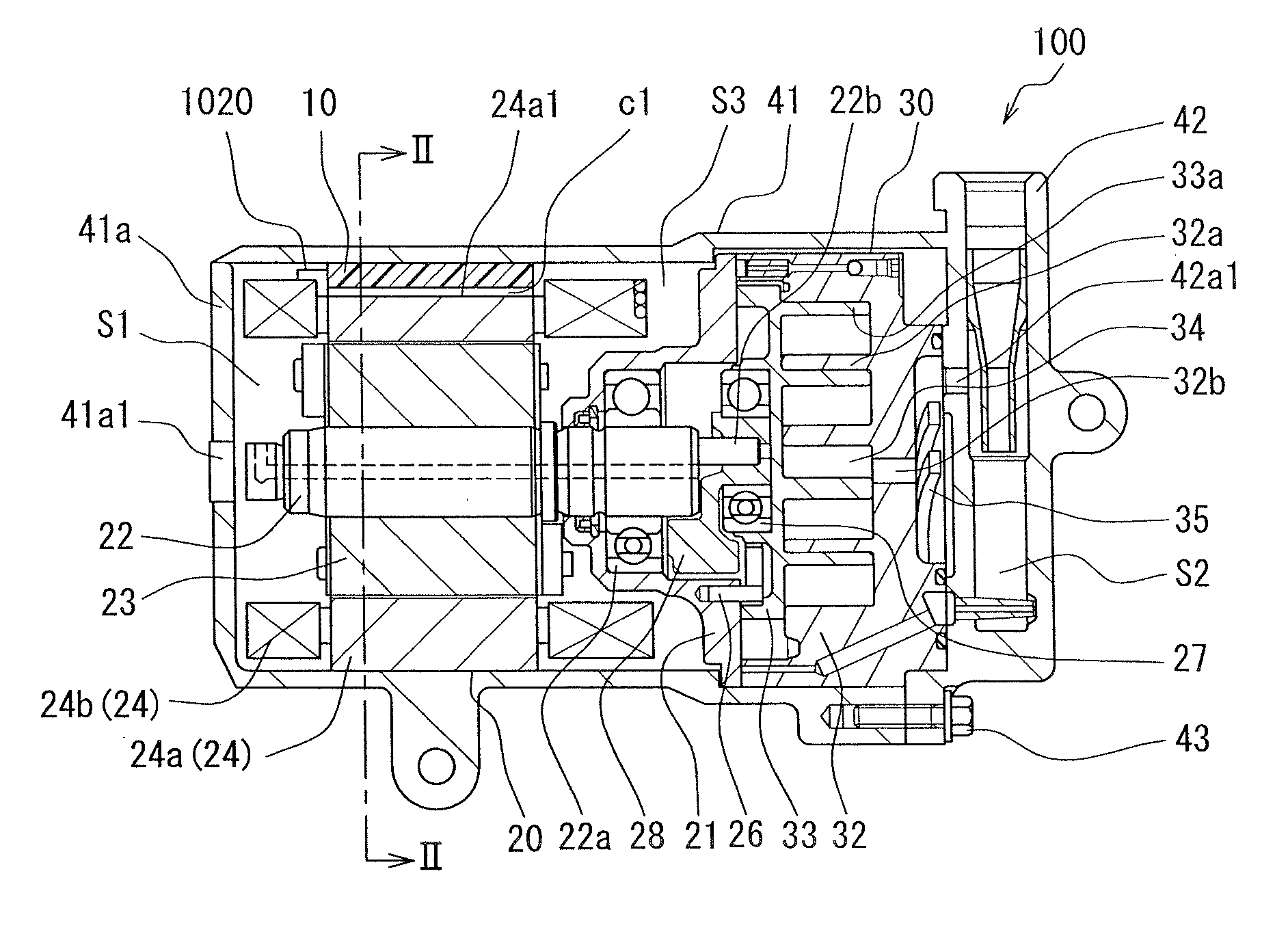
[0028]FIG. 1 shows a structure of an electric compressor 100 according to a first embodiment. Thus, in the present embodiment, an electric device according to the present invention is applied to the electric compressor 100. The electric compressor 100 is, for example, arranged in an engine compartment of a vehicle.

[0029]The electric compressor 100 includes a first housing 41 (corresponding to a housing of the present invention) and a second housing 42 (corresponding to the housing in the present invention), which are made of aluminum or aluminum alloy having excellent heat conductivity. The first housing 41 (i.e., the housing) is a member with a bottom, which is surrounded with a bottom 41a and a side wall. A portion of the first housing 41 facing the bottom 41a is opened. In the present embodiment, the first housing 41 is a member having a cylindrical shape with a bottom as an example of the housing 41, the cylindrical shape fitting to a shape of a later described electric motor 20...

second embodiment

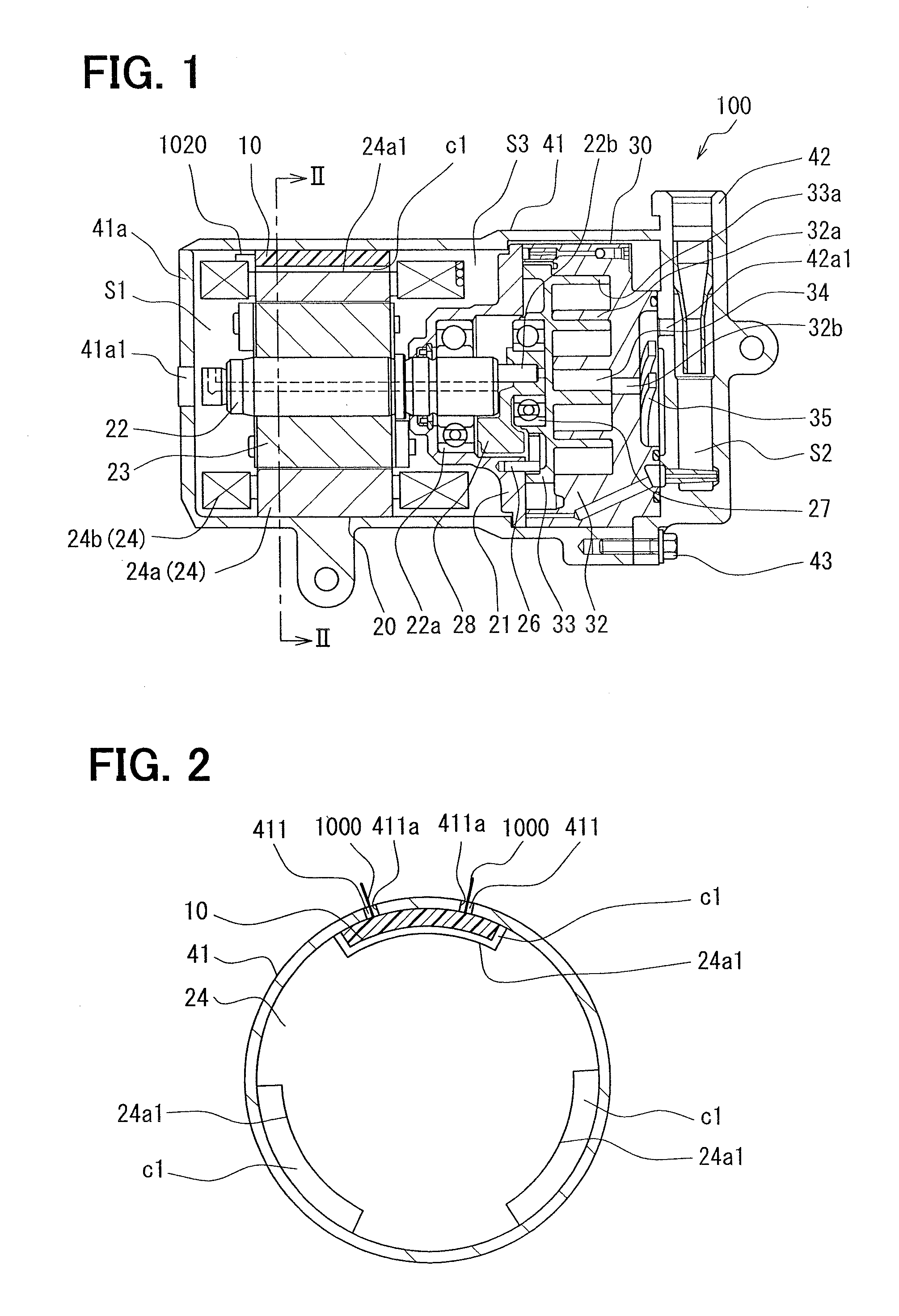
[0083]As described above, in order to restrict the leak of the cooling medium through the hole 411a, the driving circuit 10 is hermetically attached to the inner wall of the first housing 41, so that the terminal 1000 and the connection portion between the terminal 100 and the external pad 14 is separated from the cooling medium. Specifically, the terminal 1000 and the connection portion between the terminal 100 and the external pad 14 are hermetically sealed.

[0084]In the above embodiment and modifications, the attachment structure of the circuit board is applied for the electric compressor. However, the electric device according to the present invention is not limited to the above features. Specifically, the electric device according to the present invention may be applied for equipment such as a fuel pump, a water pump and oil pump other in addition to the electric compressor. Even when the circuit board in the electric device according to the present embodiment is not attached to...

third modification

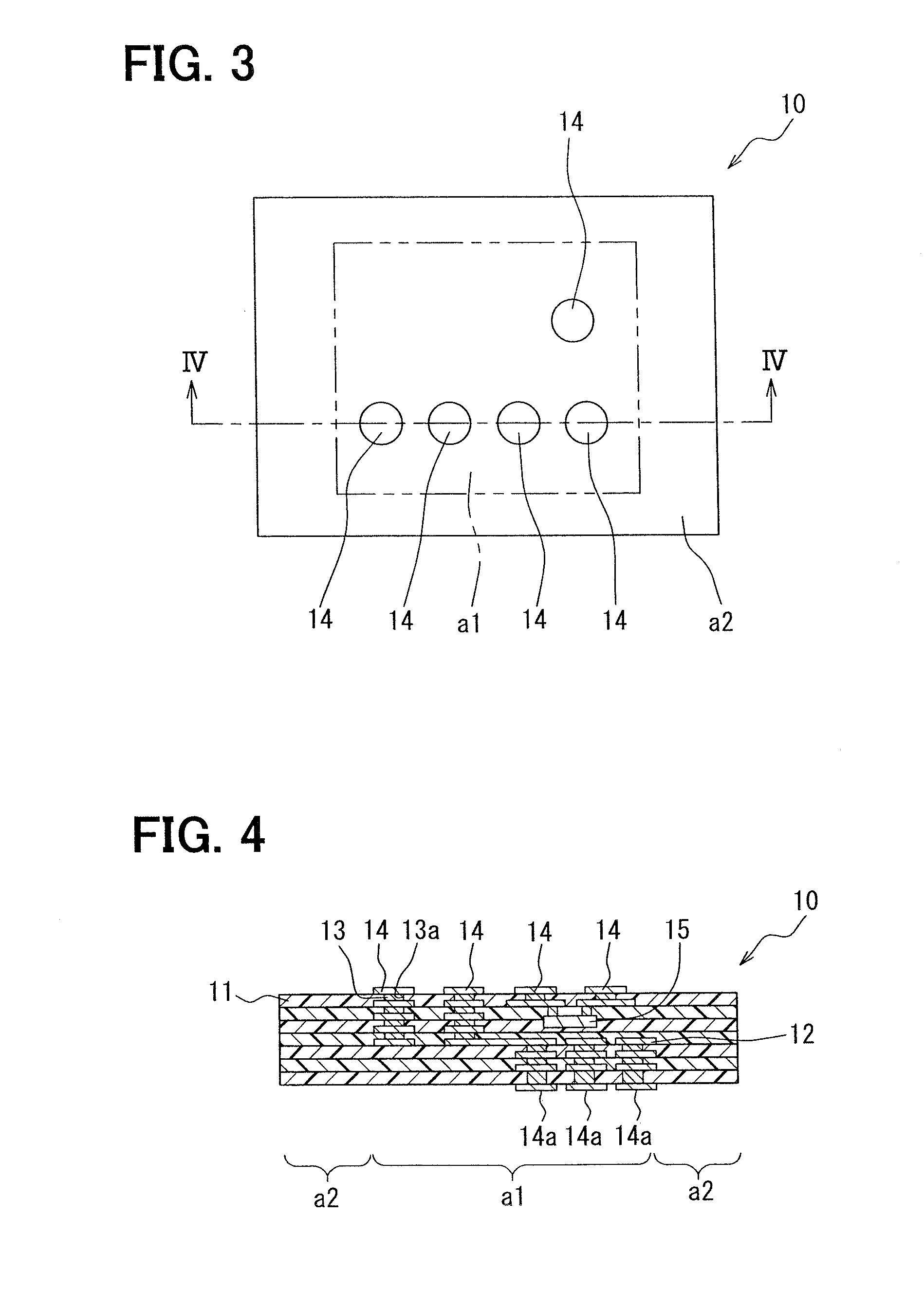
[0111]In the above embodiment, the terminal 1000 and the connection portion between the terminal 1000 and the external pad 14 are separated from the cooling medium with using the adhesive 50 and the insulation substrate (i.e., the thermo-plastic resin 11) of the circuit board 10. The present invention is not limited to this feature. As described in the third modification in FIG. 8A, the terminal 1000 and the connection portion between the terminal 1000 and the external pad 14 may be separated from the cooling medium with using a O-ring 80 and a screw 70. The above described second embodiment and the third modification have the same description largely, and therefore, the same description is not explained again, but the different features will be mainly explained.

[0112]The circuit board 10 is the same as the second embodiment basically. However, an electrode (i.e., the external pad 14 in the present modification) is formed only on the surface of the circuit board 10 facing the inner ...


PUM


Abstract

An electric device includes: a circuit board arranged in cooling medium in a housing and having an electric element and an external coupling electrode, wherein the electric element is sealed in and mounted in a substrate, and the electric element is electrically coupled with the external coupling electrode; an external coupling terminal electrically coupled with the external coupling electrode; and a separation member for separating the external coupling terminal and a connection portion between the external coupling electrode and the external coupling terminal away from the cooling medium.

Description

CROSS REFERENCE TO RELATED APPLICATIONS[0001]This application is based on Japanese Patent Applications No. 2010-86346 filed on Apr. 2, 2010, and No. 2011-30002 filed on Feb. 15, 2011, the disclosures of which are incorporated herein by reference.FIELD OF THE INVENTION[0002]The present invention relates to an electric device mounted in an electric compressor.BACKGROUND OF THE INVENTION[0003]Conventionally, an electric compressor is disclosed as an example of a device, in which an electric device is mounted, in the patent document No. 1. The electric compressor includes a housing with a cooling medium suction port and a cooling medium discharge port, a compressing mechanism unit accommodated in the housing, a driving shaft rotatably supported in the housing and transmitting a driving force to the compressing mechanism unit, a stator core accommodated in the housing and arranged on an outer periphery side in a radial direction of the driving shaft, a stator coil accommodated in the hou...

Claims


Application Information

Patent Timeline
Patent Type & Authority Applications(United States)
IPC IPC(8): F04B35/04H02K11/00H02K9/12H05K7/20
CPCF04B35/04F04C23/008F04C29/0085F04C29/047F04C2240/808H05K1/0203H01L2924/0002H05K1/185H05K7/20936H01L2924/00
Inventor YAMADA, MASAOYOSHIMURA, SATOSHIFUJII, TETSUO
Owner DENSO CORP
Why Eureka
Try Eureka