Active antenna device, network device and access point of a wireless network

a wireless network and active antenna technology, applied in the field of active antenna devices, network devices and access points of wireless networks, can solve the problems of large number of aps, and difficult reliable and efficient communication, and achieve the effects of more predictable and reliable radio links, low handover frequency, and large spacing between aps

Inactive Publication Date: 2011-11-03
SIEMENS AG
View PDF5 Cites 18 Cited by
  • Summary
  • Abstract
  • Description
  • Claims
  • Application Information

AI Technical Summary

Benefits of technology

[0009]Therefore this invention aims at providing a more predictable and reliable radio link between an AP and a wireless terminal in a wireless network and allowing a relatively large spacing between APs thus achieving a low handover frequency whereas rendering the communication less vulnerable to contentions and / or interference than in the conventional systems.
[0017]In an advantageous embodiment of the invention, the power distribution unit is provided with two wire links, such that the traffic data signal and the instruction can be transmitted separately with the traffic data signal on one wire link and the instruction on a second wire link. In this case, exchange of relatively large amounts of data on the second wire link is made possible.

Problems solved by technology

In vehicle to roadside data communication such as wireless CBTC (Communication Based Train Control) or PIS (Passenger Information Systems), for example, the mobility of a client and the resulting rapid change of channel conditions make reliable and efficient communication difficult.
Although careful planning of AP (Access Point) placement, antenna configuration and hardware setup can take into account the effects of propagation path loss, shadowing and (to some extent) multi-path propagation, other effects such as interference from other systems or temporary changes in propagation conditions are less predictable and can severely affect system performance, i.e. data throughput and link reliability.
In practice some overlap of the coverage ranges of adjacent APs is required in order to allow a smooth handover.Cost: Smaller distance between APs results in larger number of APs and thus higher equipment costs.Handover frequency: Frequent handoffs will increase overhead and reduce the throughput.
Consequently high speed vehicles demand for a larger AP spacing in order to keep the handover-induced overhead within acceptable limits.Frequency re-use: Since the RF (Radio Frequency) bandwidth is limited, dense AP deployment will lead to contention and / or interference between APs using the same RF.
This affects the efficiency of bandwidth utilization.

Method used


Image

  • Active antenna device, network device and access point of a wireless network
  • Active antenna device, network device and access point of a wireless network
  • Active antenna device, network device and access point of a wireless network

Examples


Embodiment Construction

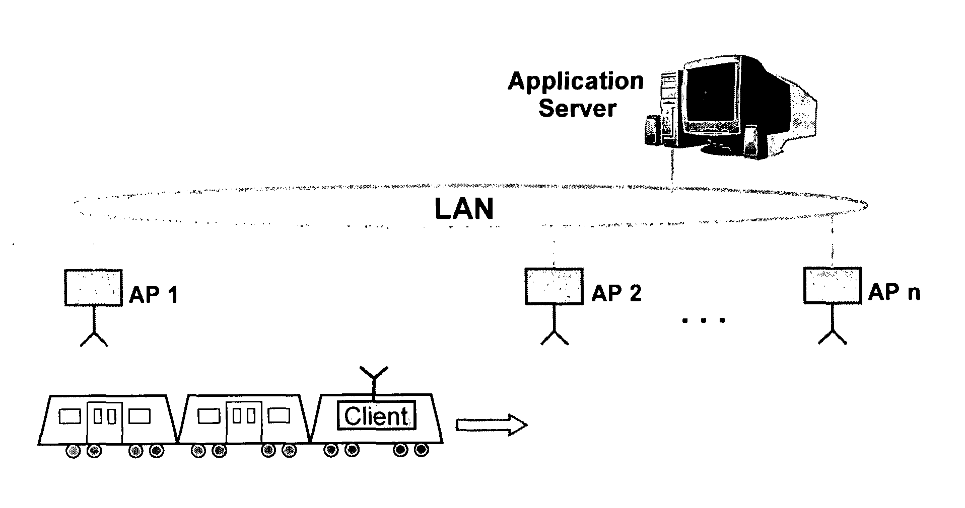
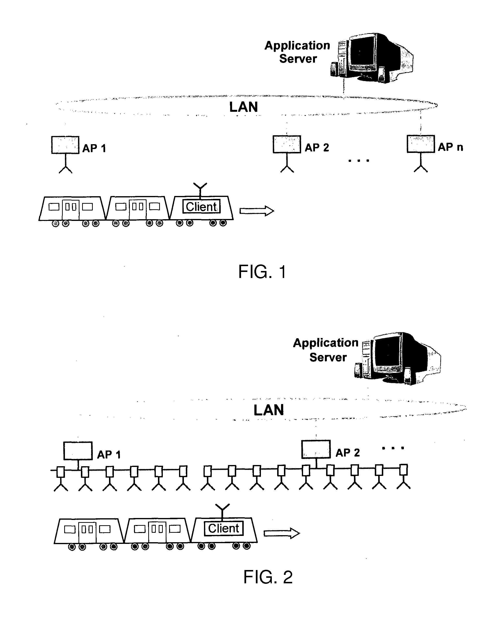
[0030]An exemplary setup of a train to trackside communication network according to the invention is given in FIG. 2. In this setup, each AP is equipped with a number of active antenna devices that are distributed along the rail, i.e. the motion path of the client. The network device and the distributed active antenna devices of an AP are coupled to each other by a wire link provided by the power distribution unit of the AP. For example, the RF port of the network device is connected to a low-loss RF transmission line (preferably coaxial cable) to which the individual active antenna devices are coupled by asymmetric power splitters or comparable coupling means. Because the RF signal loss between the network device and the active antenna devices will be different for each active antenna device due to the different cable lengths, different coupler losses and different amounts of power coupled out by the other active antenna devices, the amplification of the amplifier unit of each acti...


PUM


Abstract

An active antenna device, a network device, an access point equipped with the network device and a plurality of distributed active antenna devices form components of a communication system. The active antenna device contains an antenna unit, an amplifier unit and a control unit, wherein the amplification of the amplifier unit is controlled by the control unit according to an instruction from a management unit located in the network device. The devices achieve a low handover frequency whereas rendering the communication less vulnerable to contentions and / or interference than in the conventional systems.

Description

TECHNICAL FIELD[0001]The invention relates to an active antenna device, a network device and an access point of a wireless network, especially of a vehicle to roadside communication network.BACKGROUND TECHNOLOGY[0002]In vehicle to roadside data communication such as wireless CBTC (Communication Based Train Control) or PIS (Passenger Information Systems), for example, the mobility of a client and the resulting rapid change of channel conditions make reliable and efficient communication difficult. Although careful planning of AP (Access Point) placement, antenna configuration and hardware setup can take into account the effects of propagation path loss, shadowing and (to some extent) multi-path propagation, other effects such as interference from other systems or temporary changes in propagation conditions are less predictable and can severely affect system performance, i.e. data throughput and link reliability.[0003]In a conventional wireless network, each AP is equipped with a singl...

Claims


Application Information

Patent Timeline
Patent Type & Authority Applications(United States)
IPC IPC(8): H04B1/04H04W4/00
CPCH01Q23/00H01Q1/246
Inventor HU, ZHEN PINGKISTER, ANDREASLAMPE, MATTIASSEIFERT, MATTHIASTIAN, JI FENG
Owner SIEMENS AG
Why Eureka
Try Eureka