Electron spin resonance imaging scanner

Inactive Publication Date: 2011-11-03
GENERAL ELECTRIC CO
View PDF7 Cites 9 Cited by
  • Summary
  • Abstract
  • Description
  • Claims
  • Application Information

AI Technical Summary

Benefits of technology

[0007]The EPRI system further comprises a radio frequency signal source and pulse programmer configured together with the resistive magnet and gradient coils to generate

Problems solved by technology

EPRI however has limitations.
These limitations include sensitivity, fast relaxation time of the spin (large band width required), and high frequency of detection.
These factors mean that the spatial resolution is limited, and that absorption of radio frequency energy limits the sensitivity and ability to quantify pO2.
Pulsed EPRI to date has been limited to

Method used


Image

  • Electron spin resonance imaging scanner
  • Electron spin resonance imaging scanner
  • Electron spin resonance imaging scanner

Examples


Embodiment Construction

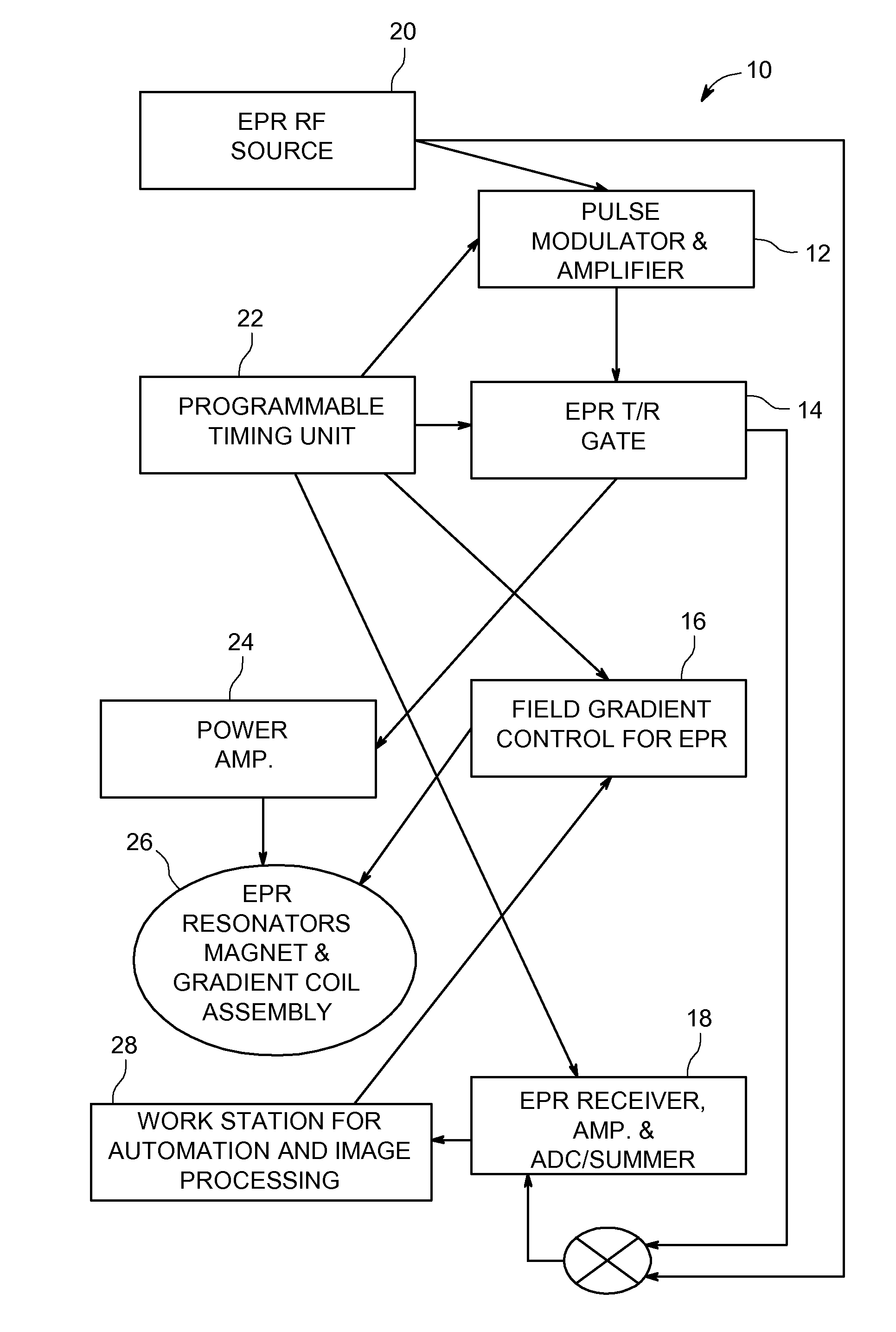
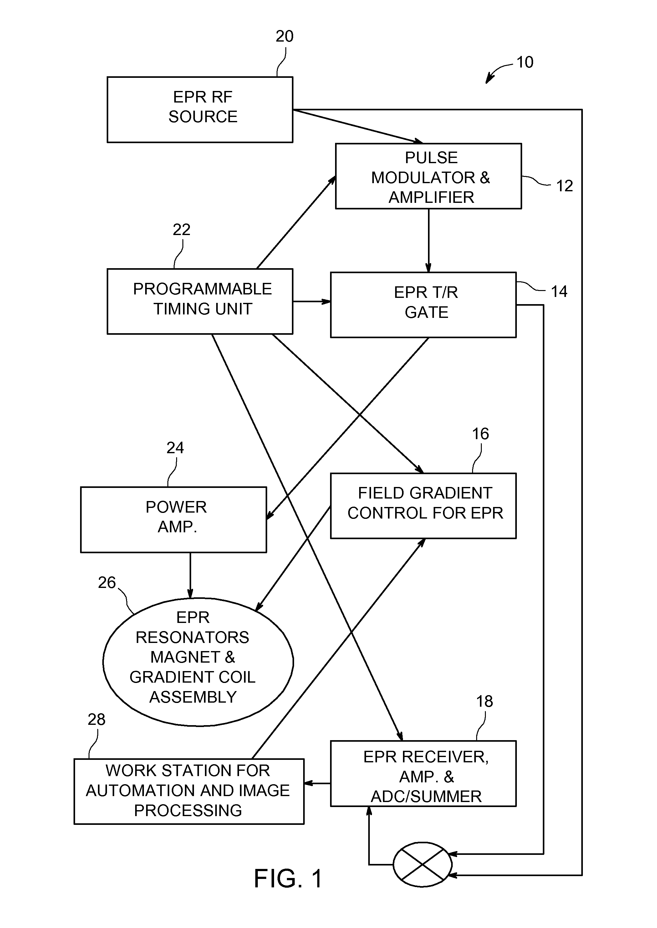
[0016]FIG. 1 is a simplified high order system diagram illustrating an electron paramagnetic resonance imaging (EPRI) system 10 that operates to quantify pO2 information associated with a human body according to one embodiment of the invention. EPRI system 10 comprises an EPR pulse modulator and amplifier module 12 having an output coupled to the input of an EPR transmit / receive gate 14, an EPR field gradient controller 16, and an EPR receiver, amplifier and ADC / summer 18. EPRI system 10 further comprises a radio frequency source 20, a programmable timing unit 22, a power amplifier 24, EPR resonators, magnet and gradient coil assembly 26, and a work station for automation and image processing 28. The magnet and gradient coil assembly 26 comprises a primary magnet for generating a static magnetic field and gradient coils for generating gradient magnetic fields.

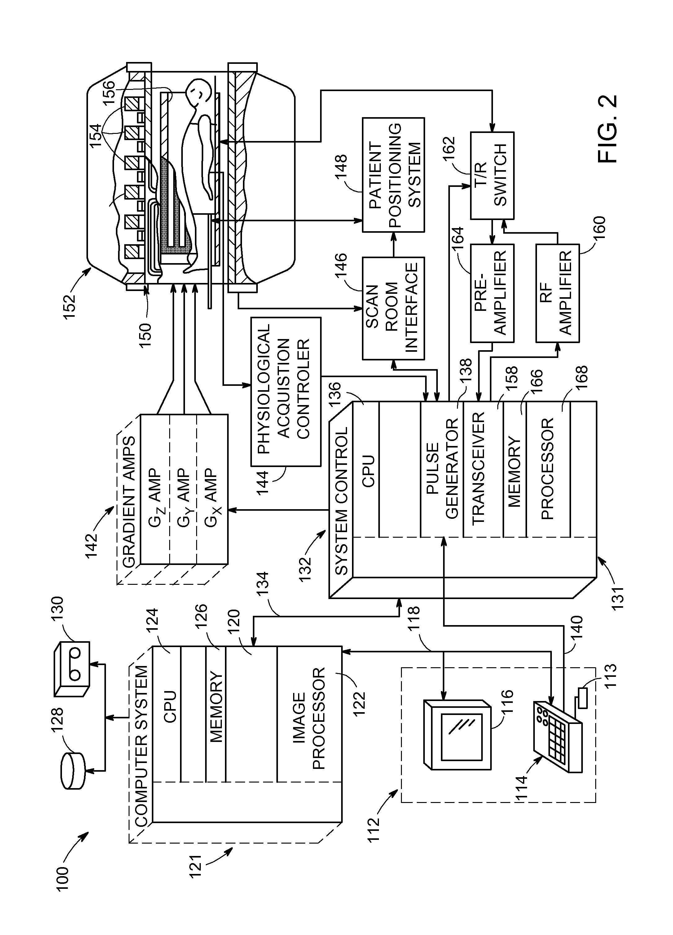
[0017]FIG. 2 is a more detailed system diagram illustrating an electron paramagnetic resonance imaging system 100 that operat...


PUM


Abstract

An electron paramagnetic resonance imaging (EPRI) system includes a resistive magnet driven by a power supply such as a power supply module to generate radio frequency signals in a substantially coherent polyphase perfect sequence scheme. The EPRI system further includes image acquisition and processing electronics configured to generate, acquire, quantify and map pO2 information associated with a free radical agent in vivo and having a resonance line width that is sensitive to oxygen and in response to the radio frequency signals without imparting harmful heating effects to a corresponding human or animal body.

Description

BACKGROUND[0001]The invention relates generally to electron paramagnetic resonance imaging (EPRI), and more particularly to an electron spin resonance imaging system that accommodates clinical applications such as, without limitation, pO2 mapping.[0002]EPRI is an imaging modality based on the imaging of exogenous electron paramagnetic resonance probes. It is thus a combination of a scanner and a contrast agent. Molecules suitable for use with EPRI to map pO2 have been developed and are well known. Mapping pO2 is of particular importance regarding, without limitation, radiotherapy planning in cancer treatment and wound healing / amputation of extremities. EPRI however has limitations. These limitations include sensitivity, fast relaxation time of the spin (large band width required), and high frequency of detection. These factors mean that the spatial resolution is limited, and that absorption of radio frequency energy limits the sensitivity and ability to quantify pO2.[0003]Pulsed EPR...

Claims


Application Information

Patent Timeline
IPC IPC(8): A61B5/055
CPCA61B5/055G01R33/60A61B5/14542
Inventor ARDENKJAER-LARSEN, JAN-HENRIKMURRAY, JONATHAN ALANROBB, FRASER JOHN LAINGHURD, RALPH EUGENETARACILA, VICTOR
Owner GENERAL ELECTRIC CO
Why Eureka
Try Eureka