Hybrid electric vehicle generation system

Inactive Publication Date: 2011-11-10
HINDS MICHAEL
View PDF2 Cites 5 Cited by
  • Summary
  • Abstract
  • Description
  • Claims
  • Application Information

AI Technical Summary

Benefits of technology

[0026]It is a still further object of the invention to provide an electric power generat

Problems solved by technology

Initially, there were external combustion vehicles powered by steam followed by internal combustion vehicles powered by hydrocarbons the

Method used


Image

  • Hybrid electric vehicle generation system
  • Hybrid electric vehicle generation system
  • Hybrid electric vehicle generation system

Examples


Embodiment Construction

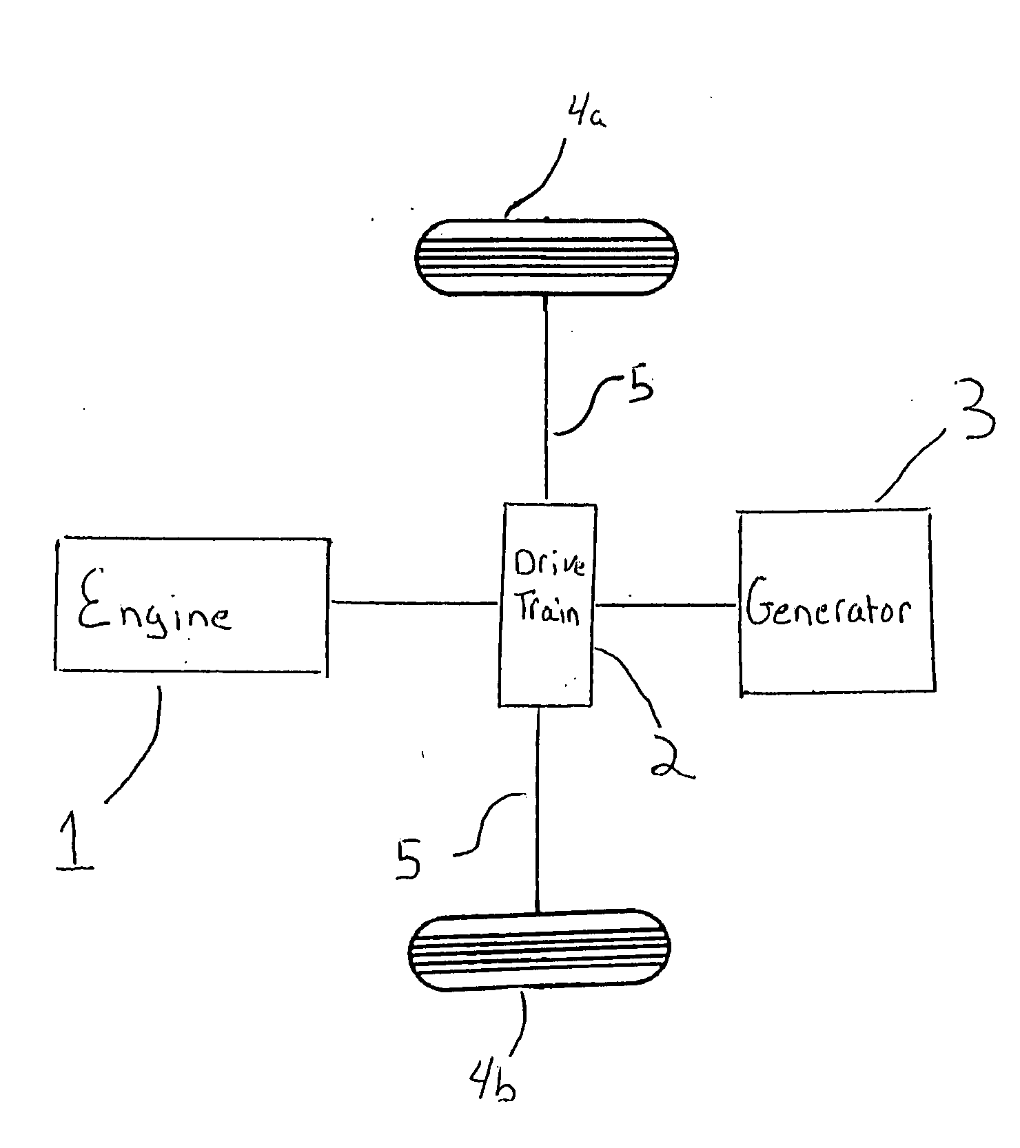
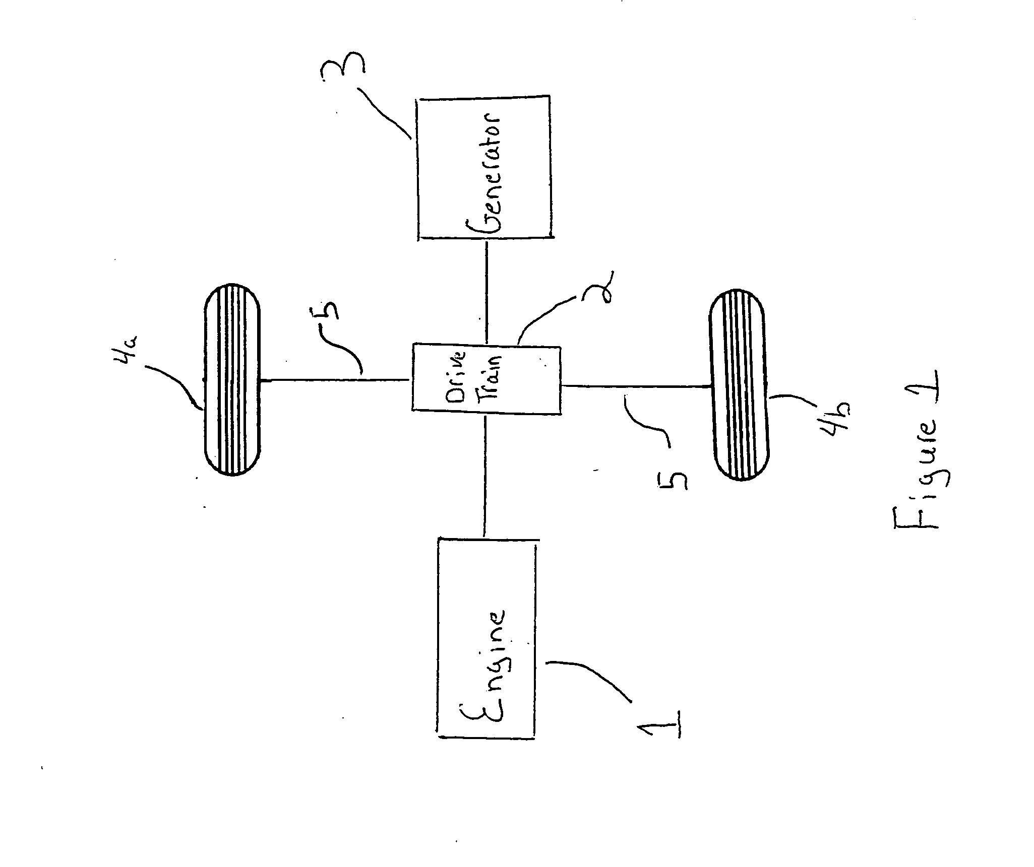
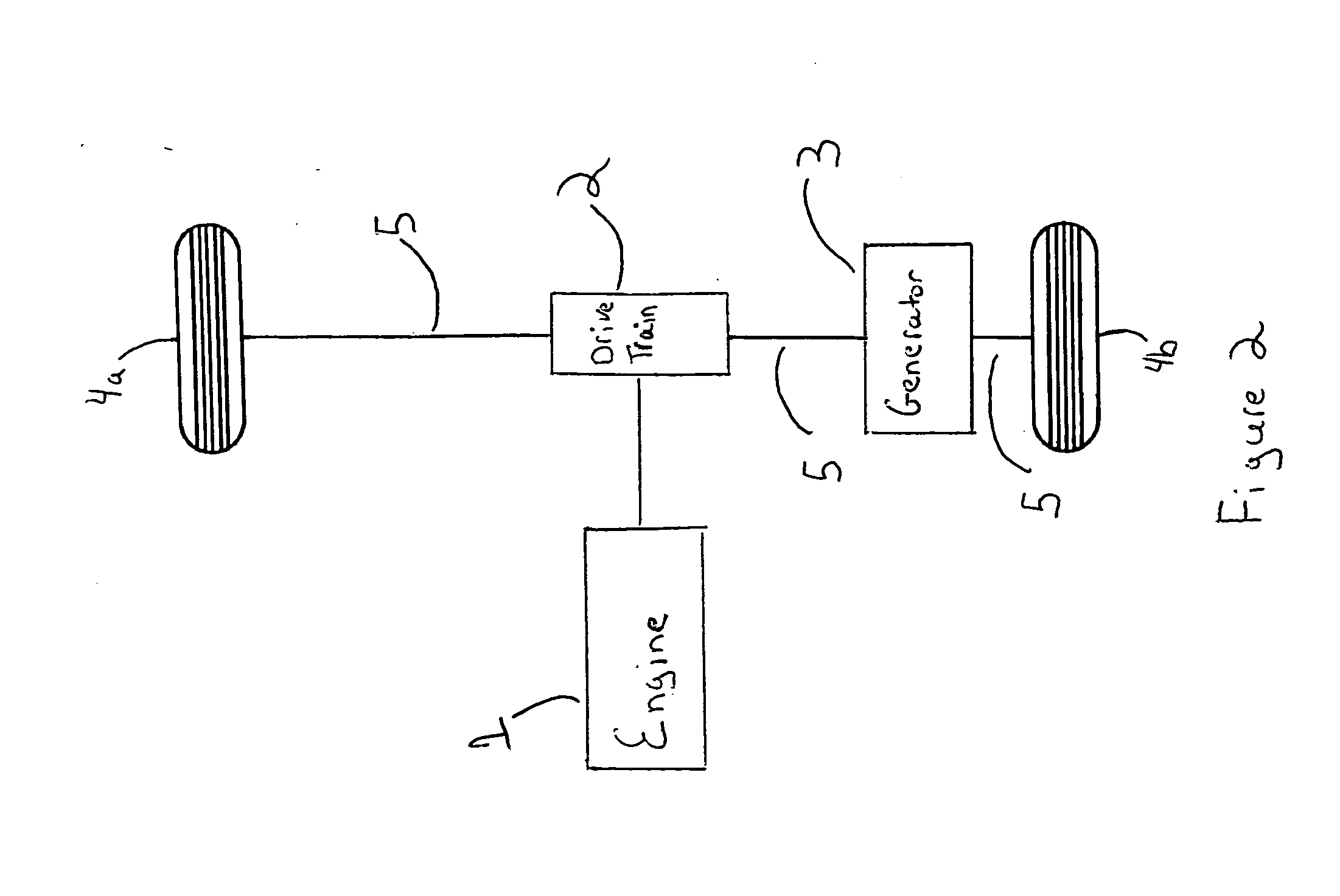
[0039]In one embodiment of the invention there is an engine and a transmission connected to the engine. The transmission is connected to a front drive shaft. There is a rear drive shaft that is connected to a rear differential. The rear differential provides power from the engine to the rear wheels. As the engine operates, the engine power is transmitted by the drive shaft through the rear differential to each wheel.

[0040]In accordance with the present invention the motive power of the engine can be used to turn a generator to generate electricity for use by the vehicle. This electrical power may operate accessories used in the vehicle such as radio, light, etc. or may be stored in a battery.

[0041]The generator can be positioned in any number of locations in the vehicle. In one embodiment the generator is between the engine and the transmission. In another embodiment the generator may be between the transmission and the front drive shaft and the rear drive shaft. The generator may a...


PUM


Abstract

The present invention is directed to a generation means for generating electrical power to operate vehicle systems and/or for recharging batteries used by electric and/or hybrid cars. The present invention may also generate electric power to operate an electric motor that can also drive a vehicle. The present invention may also use the electric power generated for other uses as well. It comprises an engine that is connected to at least one rotatable member connected for rotation therewith and at least one generator that is connected to the rotatable member through a rotor in said generator to generate electrical energy.

Description

[0001]This application claims priority on U.S. Provisional Application Ser. No. 61 / 343,873 filed on May 5, 2010, the disclosures of which are incorporated herein by reference.FIELD OF THE INVENTION[0002]The present invention is directed to improvements in electric, hybrid and hydrocarbon fuel powered automobiles.BACKGROUND OF THE INVENTION[0003]For over one hundred years automobiles have been powered by a variety of power generation systems. Initially, there were external combustion vehicles powered by steam followed by internal combustion vehicles powered by hydrocarbons there have also been vehicles powered by electricity, although until recently battery technology placed severe limitations on such vehicles. Recently there have been a variety of vehicles called hybrid electric vehicles, which combine a conventional propulsion system with an on board rechargeable system to achieve better fuel economy.[0004]In internal combustion engines used in a variety of vehicles, the engine pro...

Claims


Application Information

Patent Timeline
IPC IPC(8): B60K6/50H02K7/18H02K47/14F16H37/06B60K6/20H02K53/00
CPCB60K6/48B60K2006/4808H02K53/00Y10T74/19074Y02T10/626Y02T10/641Y02T10/6221Y02T10/62Y02T10/64
Inventor HINDS, MICHAEL
Owner HINDS MICHAEL
Why Eureka
Try Eureka