

Fiber application machine provided with flexible fiber conveying tubes arranged within a cold sheath
a technology of conveying tube and fiber, which is applied in the direction of tubular elements, heat exchange apparatus, lighting and heating apparatus, etc., can solve the problems of difficult implementation of compressed air cooling system, difficult cooling of compressed air, and clogging of application head and flexible tube, etc., and achieves the effect of simple construction
- Summary
- Abstract
- Description
- Claims
- Application Information
AI Technical Summary
Benefits of technology
Problems solved by technology
Method used
Image

Examples
first embodiment
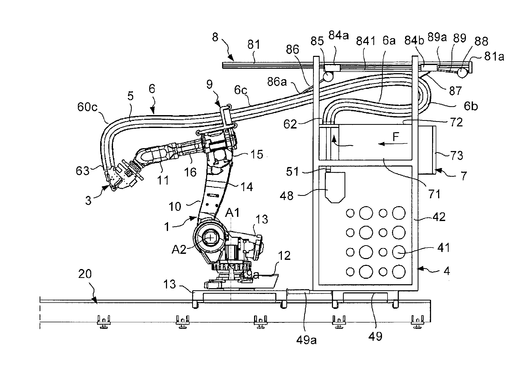
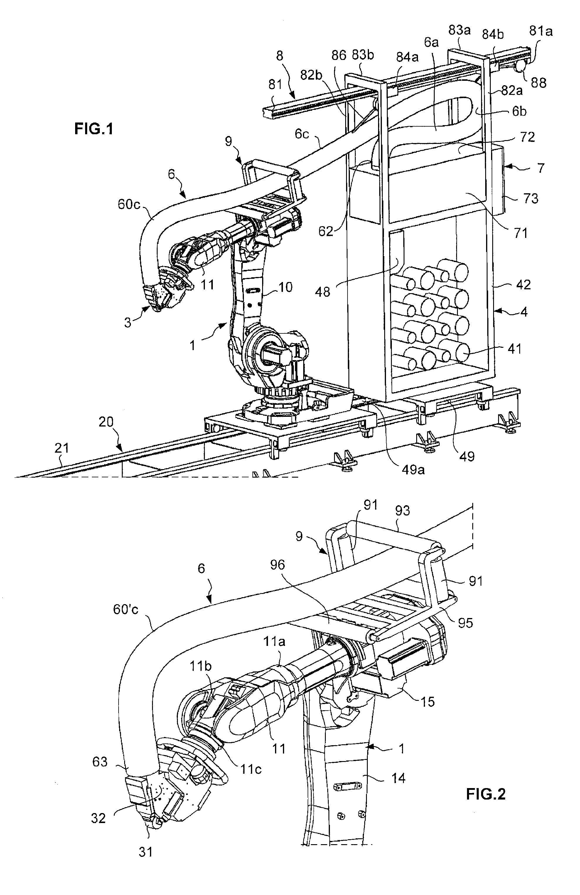
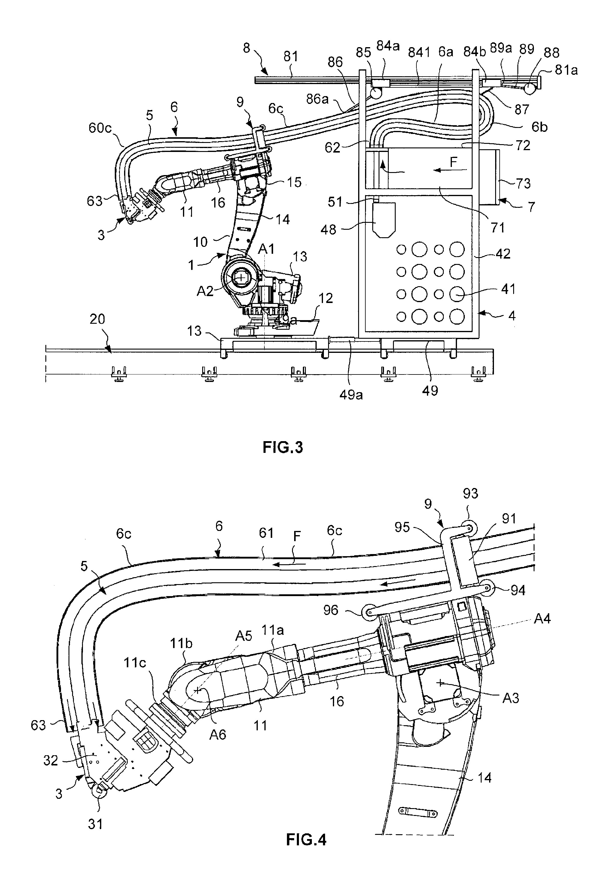
FIGS. 1 to 6B illustrate the invention. With reference to FIG. 1, the placement machine includes a displacement system 1 composed of a six axis robot type poly-articulated arm 10, mounted mobile on a linear axis 20, an application head 3 mounted to the end wrist 11 of the poly-articulated arm, a fiber storage 4 for storing the fibers, a fiber conveyor 5 (FIG. 3) for conveying fibers from the fiber storage to the application head.
With reference to FIGS. 3 and 4, the poly-articulated arm 10 includes a first section or base 12 and a second, third, forth and fifth sections, 13, 14, 15 and 16, respectively, pivotally assembled to each other around rotation axis A1, A2, A3 and A4, and an end wrist 11 including the last three sections 11a, 11b and 11c of the arm. The end wrist includes a first section 11a whereby the wrist is assembled to the sixth section 16 of the arm, such that the wrist is rotationally mounted around axis A4, a second section 11b pivotally mounted on first section arou...
second embodiment
FIGS. 7 to 10 illustrate a second embodiment in which the fiber placement head is mounted on a gantry type displacement system. The placement machine includes a gantry type displacement system 101 with an end wrist 111, a placement head 103 connected to a fiber storage 104 by a fiber conveyor comprising, as before, flexible tubes placed within a sheath 106.
The gantry type displacement system 101 includes a first carriage 112 mounted mobile along a first horizontal direction X between two parallel support bars 113a of a gantry 113, a second carriage 114 (FIG. 9) mounted mobile on the first carriage 112 along a second horizontal direction Y perpendicular to the first one, and a third carriage 115, also called sliding carriage, mounted vertically mobile on the second carriage 114 along a third vertical direction Z. The displacements of the three carriages are made possible through driver embedded on each one of them, and servo-controlled by a main controller of the machine. The wrist 1...
third embodiment
FIGS. 10 and 11 illustrate a third embodiment wherein the fiber placement head is mounted on a columnar type displacement system. The placement machine includes a columnar type displacement system 201 with a wrist 211, a placement head 203 connected to fiber storage 204 by fiber conveyor comprising flexible tubes placed in a sheath 206.
The displacement system 201 comprises a vertical column 212 mounted mobile along a first horizontal direction X on two horizontal rails 213, and a carriage 214, or sliding carriage, mounted vertically mobile on the column along a vertical direction Z, the displacements of the column and the carriage being performed by the driver embedded and servo-controlled by a main controller of the machine. The wrist 211, of a three axis robot wrist type, has three sections 211a, 211b, 211c, such as described previously. The wrist is pivotally mounted from its first section 211a to a side end of the carriage around a horizontal rotation axis. The third section 211...
PUM
 Abstract
Description
Claims
Application Information