
Method for generating optical tomographic information, optical tomographic information generating apparatus, and storage medium

Active Publication Date: 2011-11-10
FUJIFILM CORP
View PDF14 Cites 0 Cited by
  • Summary
  • Abstract
  • Description
  • Claims
  • Application Information

AI Technical Summary

Benefits of technology

[0021]According to the present invention as described above, because the absorption coefficient is set beforehand as well as the scattering coefficient of a living body (the subject), the inverse problem calculation need only be performed for the intensity of the fluorescence, and therefore, a processing load for generating optical tomographic information representing a region of the phosphor inside the subject may be moderated, and a shortening of a processing duration may be promoted. In addition, an intensity measurement of light for generating the optical tomographic information need be carried out only for fluorescence emitted from the subject, and therefore, the present invention has advantageous effects in that a simplification of apparatus and a shortening of measurement duration may be promoted.

Problems solved by technology

This inverse problem calculation imposes a larger calculation load than a forward problem calculation and requires more time to calculate.

Method used


Image

  • Method for generating optical tomographic information, optical tomographic information generating apparatus, and storage medium
  • Method for generating optical tomographic information, optical tomographic information generating apparatus, and storage medium
  • Method for generating optical tomographic information, optical tomographic information generating apparatus, and storage medium

Examples


Embodiment Construction

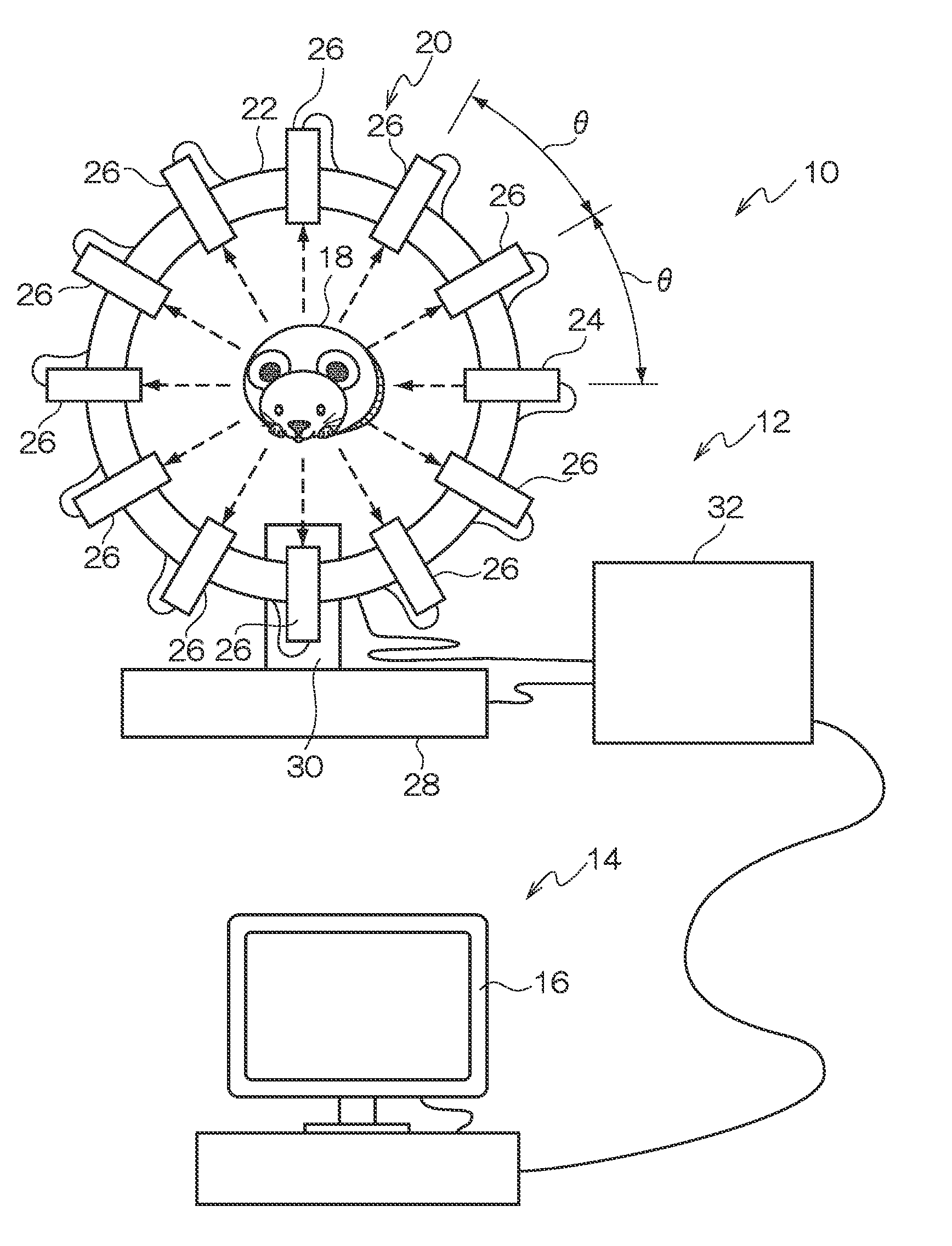
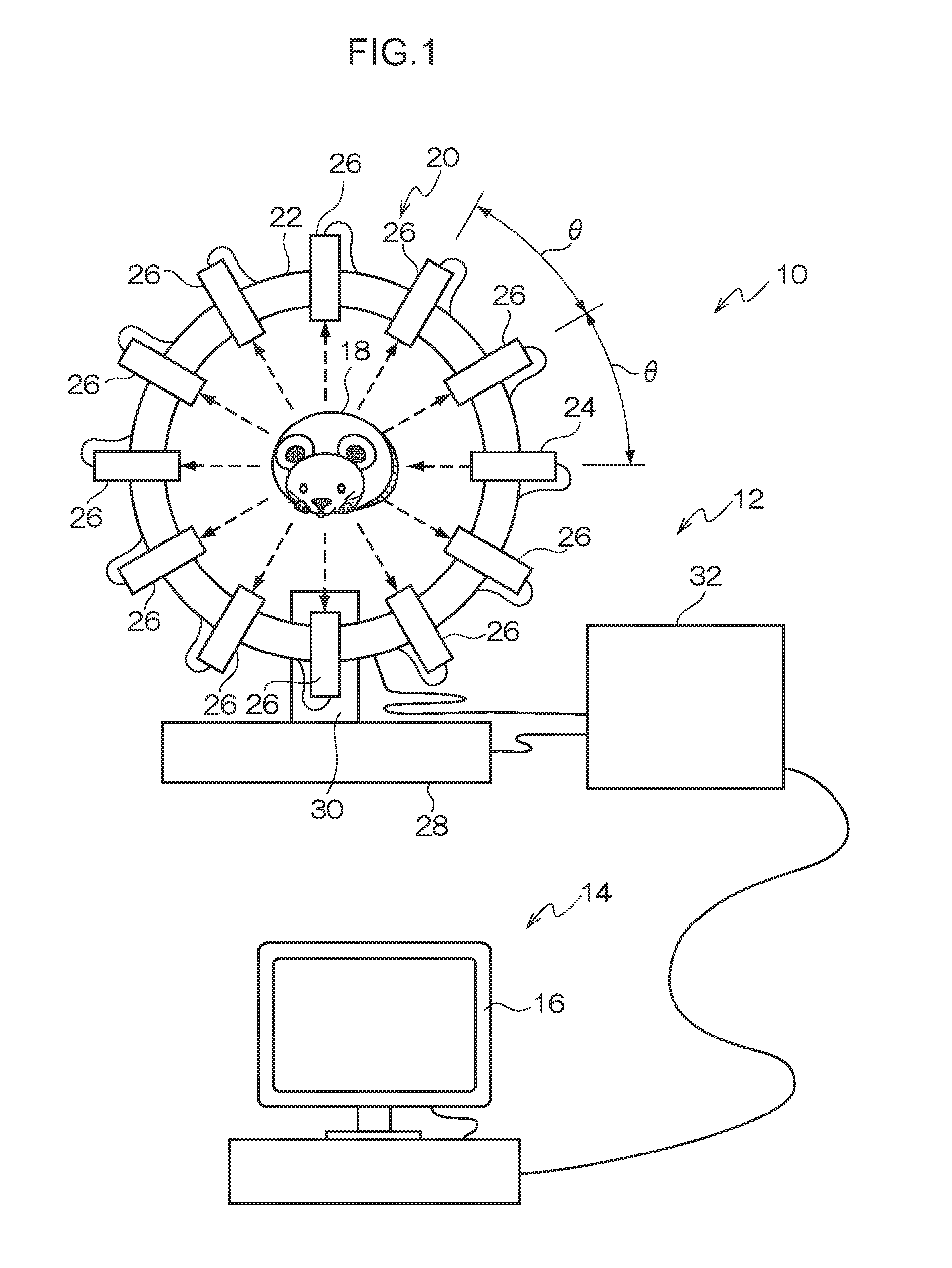
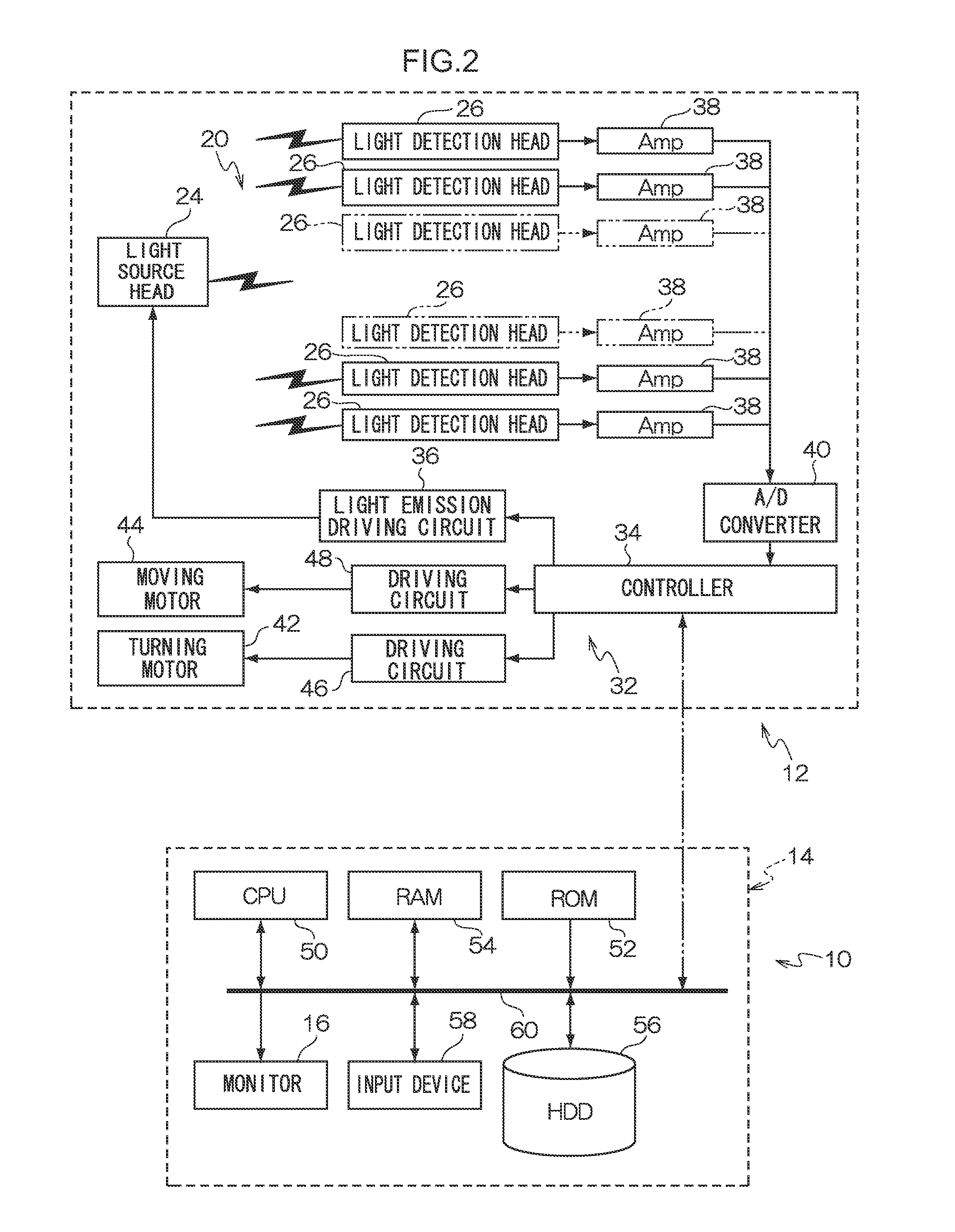
[0029]Herebelow, an exemplary embodiment of the present invention is described while referring to the attached drawings. FIG. 1 illustrates schematic structure of an optical tomographic observation apparatus 10 relating to the present exemplary embodiment. This optical tomographic observation apparatus 10 includes a measurement section 12 and an image forming section 14 that carries out image formation (signal processing) on the basis of electronic signals outputted from the measurement section 12. A monitor 16 such as a CRT, an LCD or the like is provided at the image forming section 14 to serve as a display section. Images based on measurement results from the measurement section 12 are displayed at the monitor 16.

[0030]At the optical tomographic observation apparatus 10, a living body such as a small animal or the like (for example, a nude mouse) serves as a subject 18 that is a target of observation. Images based on optical tomographic information obtained from the subject 18 (h...


PUM


Abstract

Measurement data of intensities of fluorescence obtained by directing excitation light onto a subject is acquired. An initial value of an absorption coefficient of the phosphor is set on the basis of a concentration distribution of the phosphor, an intensity distribution of the fluorescence on the basis of an absorption coefficient and a diffusion coefficient (reduced scattering coefficient) of the subject, which are set beforehand, are calculated, and the measurement data is compared with the calculation result. If these are found not to be matched, an absorption coefficient of the phosphor at which the error will be a minimum is estimated by performing an inverse problem calculation using a mathematical model. The calculation of the intensity distribution of the fluorescence and evaluation of the error from the obtained concentration distribution are repeated using the absorption coefficient, and a concentration distribution for which the error is the minimum is acquired.

Description

TECHNICAL FIELD[0001]The present invention relates to using light for tomography, and more particularly relates to a method for generating optical tomographic information that illuminates excitation light and may acquire optical tomographic images containing distributions of a phosphor that is caused to luminescence by the excitation light, and to an optical tomographic information generating apparatus and a storage medium at which an optical tomographic information generating program is stored.BACKGROUND ART[0002]Methods of acquiring tomographic images of living bodies and the like include X-ray computed tomography (CT) using X-rays, ultrasound CT using ultrasound, NMR-CT employing nuclear magnetic resonance, proton CT using beams of particles such as protons, and so forth. It is known that living bodies are transmissive to light. Thus, optical CT using light for tomographic images of small animals has been proposed (for example, see Patent Reference 1: Japanese Patent Application ...

Claims


Application Information

Patent Timeline
IPC IPC(8): G01N21/64
CPCA61B5/0073A61B2503/40A61B5/1075
Inventor YAMAMOTO, HIROAKIYAMADA, YUKIOOKAWA, SHINPEI
Owner FUJIFILM CORP
Learn More