Battery Tabs and Method of Making the Same

a battery tab and tab technology, applied in the field of battery packs, can solve the problems of less robust weld than, mechanically fastened joints are prone to loosening of joints, and dramatically reduce the robustness of welds, so as to achieve less robust welds, more robust joints, and greater corrosion resistance.

Inactive Publication Date: 2011-11-10
EMS ENGINEERED MATERIALS SOLUTIONS LLC
View PDF2 Cites 23 Cited by
  • Summary
  • Abstract
  • Description
  • Claims
  • Application Information

AI Technical Summary

Benefits of technology

[0010]It is an object of the present invention to create more robust joints (welds), with significantly greater corrosion resistance than with the other technologies that are employed such as mechanical fastening and ultrasonic and laser welding. Mechanically fastened joints are prone to loosening of the joints over time and arcing between the terminals. Ultrasonic welding creates solid state welds of dissimilar metals, however, the incompatibility of the metals results in a less robust weld than if like-metals are joined. Ultrasonic welding like-metal joints produces a more robust weld than when dissimilar welds are produced. Laser welding, or other non-solid-state welding methods, produces second phases in the mixed-metal weld zone, which can dramatically reduce the robustness of the weld. The dissimilar metals joints created with mechanically fastened joints, ultrasonic, and laser welds have a high potential for galvanic corrosion. The like-metal joints created with bimetallic terminals in accordance with the present disclosure have no potential for galvanic corrosion.

Problems solved by technology

Mechanically fastened joints are prone to loosening of the joints over time and arcing between the terminals.
Ultrasonic welding creates solid state welds of dissimilar metals, however, the incompatibility of the metals results in a less robust weld than if like-metals are joined.
Laser welding, or other non-solid-state welding methods, produces second phases in the mixed-metal weld zone, which can dramatically reduce the robustness of the weld.
The dissimilar metals joints created with mechanically fastened joints, ultrasonic, and laser welds have a high potential for galvanic corrosion.

Method used


Image

  • Battery Tabs and Method of Making the Same
  • Battery Tabs and Method of Making the Same
  • Battery Tabs and Method of Making the Same

Examples


Embodiment Construction

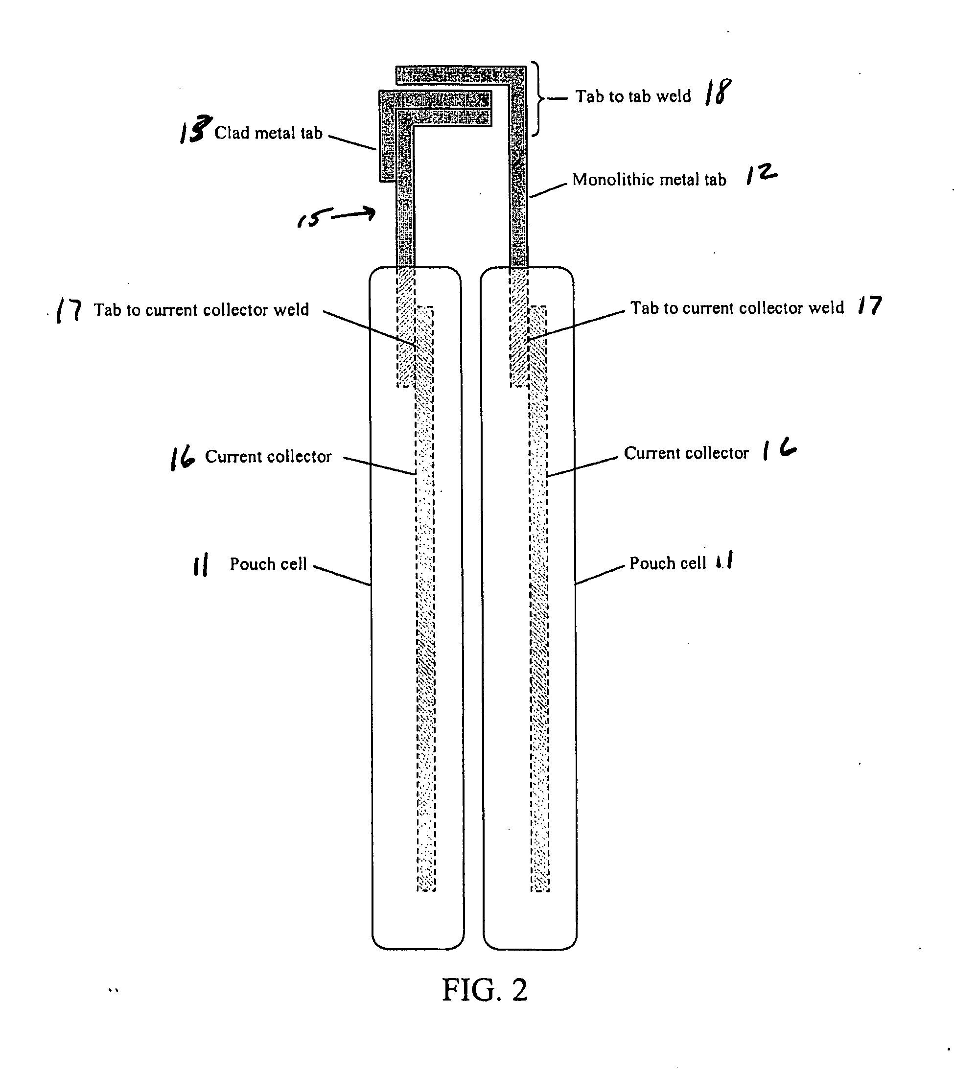
[0016]Referring to the FIGS. 1-3 for a clearer understanding of the invention, it may be seen that the preferred embodiment of the battery tab contemplates a bimetallic strip made up of the materials used as the Li-ion cell current collectors, such as copper C and aluminum Al. The bimetallic strip is to be used as, at least one, of the Li-ion pouch cell terminals. At least one edge of the bimetallic strip has one of the metallic components removed by such means as chemical or electrochemical etching, mechanical milling, skiving, or grinding. The bimetallic strip can be produced with a number of technologies including roll bonding, plating, explosion cladding, diffusion bonding, and the like.

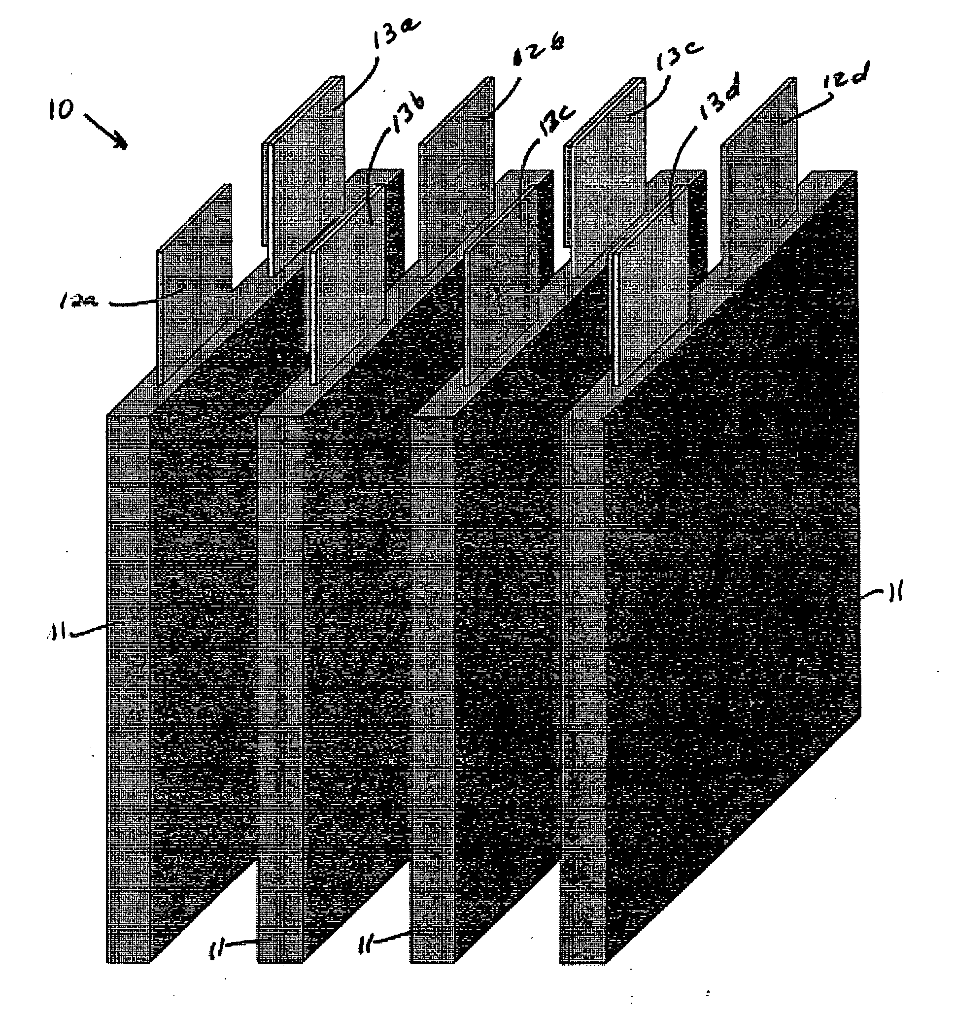
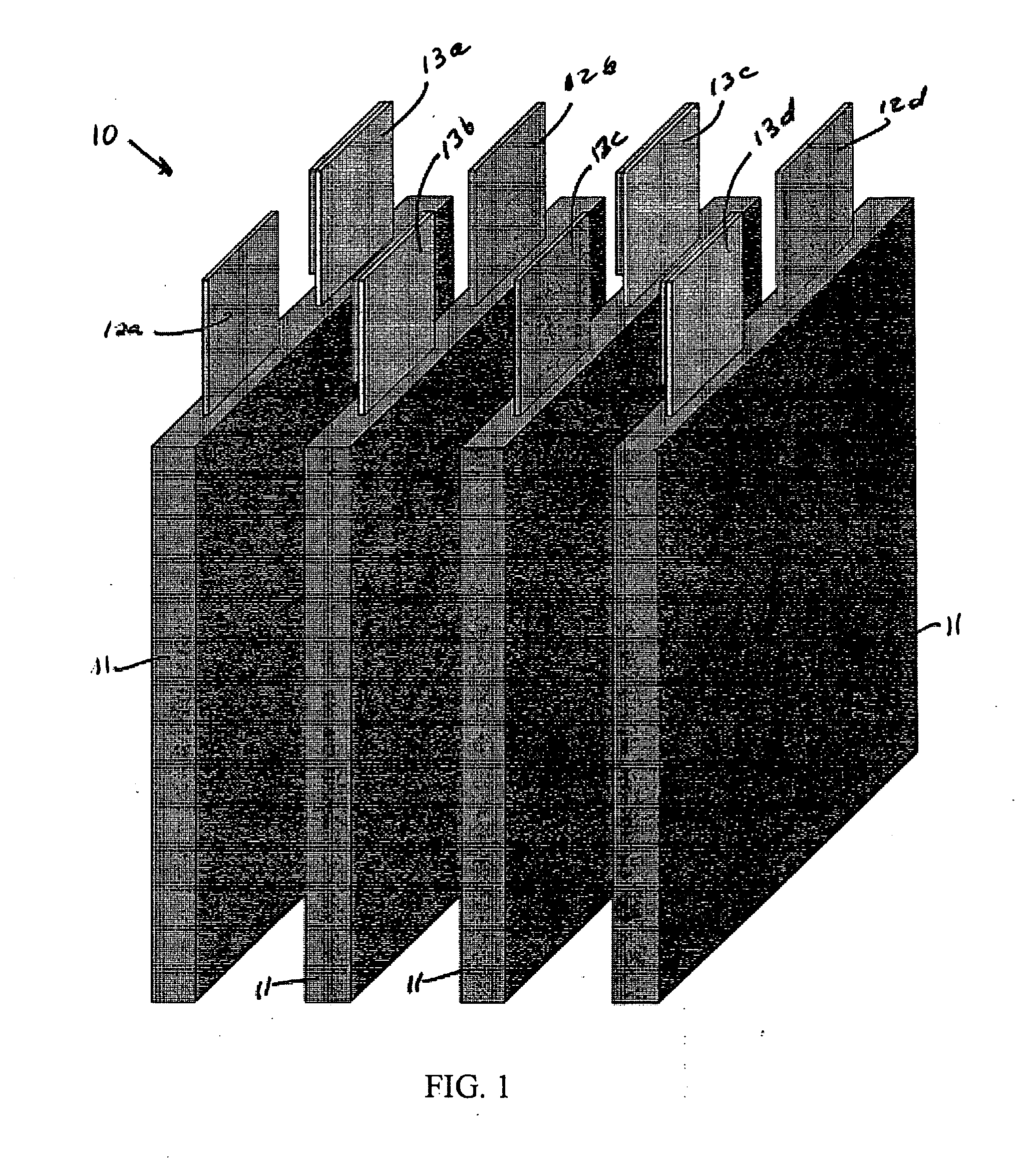
[0017]Referring to FIG. 1, disclose a Battery pack 10 with four Li-ion pouch cells, 11a, b, c, and d. Each cell has one monolithic metal (such as copper) terminal 12a, b, c, or d, and one bimetallic terminal 13a, b, c, or d. The cells 11 are arranged in a series configuration such the bimetallic ...


PUM

PropertyMeasurementUnit
resistanceaaaaaaaaaa
voltageaaaaaaaaaa
currentaaaaaaaaaa

Abstract

A terminal for a Li-ion battery cell utilizes a bimetallic strip formed from the materials used as the Li-ion cell current collectors, such as copper and aluminum. The bimetallic strip is to be used as, at least one, of the Li-ion pouch cell terminals. At least one portion of the bimetallic strip has one of the metallic components removed by such means as chemical or electrochemical etching, mechanical milling, skiving, or grinding, the remaining component being connected to the collector and the other end of the strip serving as the terminal.

Description

BACKGROUND OF THE INVENTION[0001]This application claims priority from Provisional U.S. Patent Application No. 61 / 340,319 filed Mar. 15, 2010.[0002]The present invention relates to the field of battery packs and more particularly to the joining of battery tabs from battery cells to make battery packs. Battery packs are designed to deliver a particular voltage and current, greater than an individual cell, by connecting individual battery cells in series and / or parallel configurations. Battery cells connected in series produce an increase in the voltage, and those connected in parallel produce an increase in the current. Batteries are connected in series when the positive and negative terminals of the battery are electrically joined. When a positive terminal is joined to another positive terminal, and the negative terminal is joined to another to negative terminal, then the batteries are connected in parallel.[0003]Joining of battery terminals requires an electrical path be produced b...

Claims


Application Information

Patent Timeline
Patent Type & Authority Applications(United States)
IPC IPC(8): H01M2/30H01M10/02H01M6/42H01M50/105H01M50/178H01M50/55H01M50/557H01M50/562
CPCH01M2/0207H01M2/0212Y02E60/122H01M4/661H01M10/0525H01M2/30Y02E60/10H01M50/557H01M50/562H01M50/105H01M50/55H01M50/178
Inventor TUFFILE, CHARLES
Owner EMS ENGINEERED MATERIALS SOLUTIONS LLC
Why Eureka
Try Eureka