
Applicators for microneedles

Active Publication Date: 2011-11-10
CORIUM PHARMA SOLUTIONS INC
View PDF1 Cites 190 Cited by
  • Summary
  • Abstract
  • Description
  • Claims
  • Application Information

AI Technical Summary

Benefits of technology

[0029]In another aspect, any of the applicator embodiments described herein further comprises a safety mechanism to prevent movement of the actuation member in a direction that deploys the microprojection array.
[0030

Problems solved by technology

In addition to cost, integrity and sterility, a further issue with microneedle arrays is bioavailability of the active agent.
When a drug is delivered orally, the resulting blood levels may exhibit substantial variation among patients due to metabolism and other factors, but minimal therapeutic levels can be assured for most patients, for example, because the rate of metabolism has an upper limit and because there is long experience with the absorption of many drugs from oral formulations.
On the other hand, with a conventional transdermal patch, differences in skin permeability are an additional factor leading to differences in bioavailability.
Particular concern exists, of course, if the enhancement is small in particular patient populations so that the administration of the drug will not produce a therapeutically effective dosing (e.g., adequate blood levels) in those populations.
However, a limitation of this earlier approach is that the energy delivered to the microstructure array is both limited and variable.
In some other prior art applicator designs, the energy storage element, such as a spring or elastic element, may exert forces on one or more components of the applicators, leading to dimensional distortion and creep over an extended period of time.
These effects are undesirable as they lead to variations in the applicator geometry and a loss in the stored elastic energy over time.

Method used


Image

  • Applicators for microneedles
  • Applicators for microneedles
  • Applicators for microneedles

Examples


example 1

Comparative Testing of Applicators

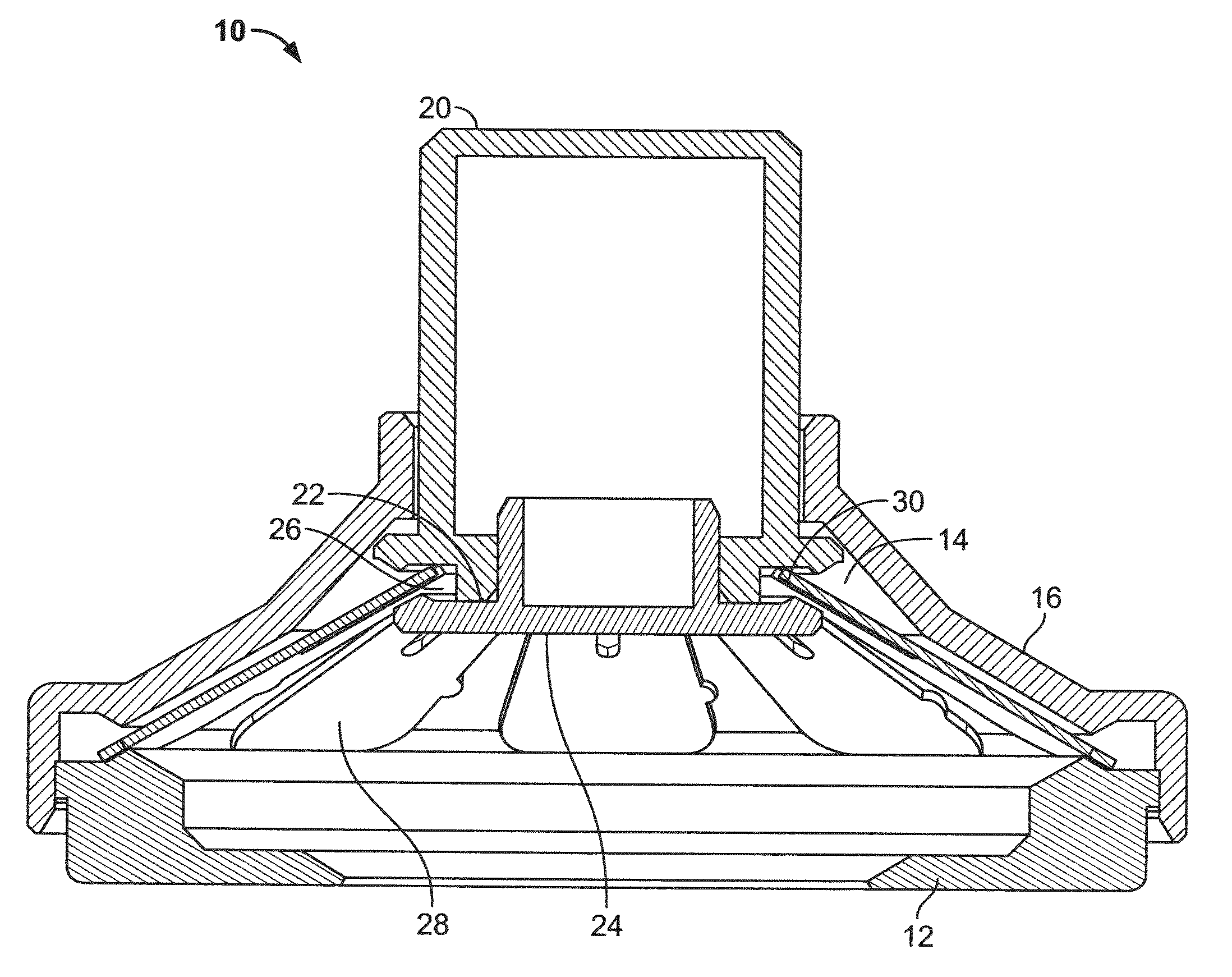
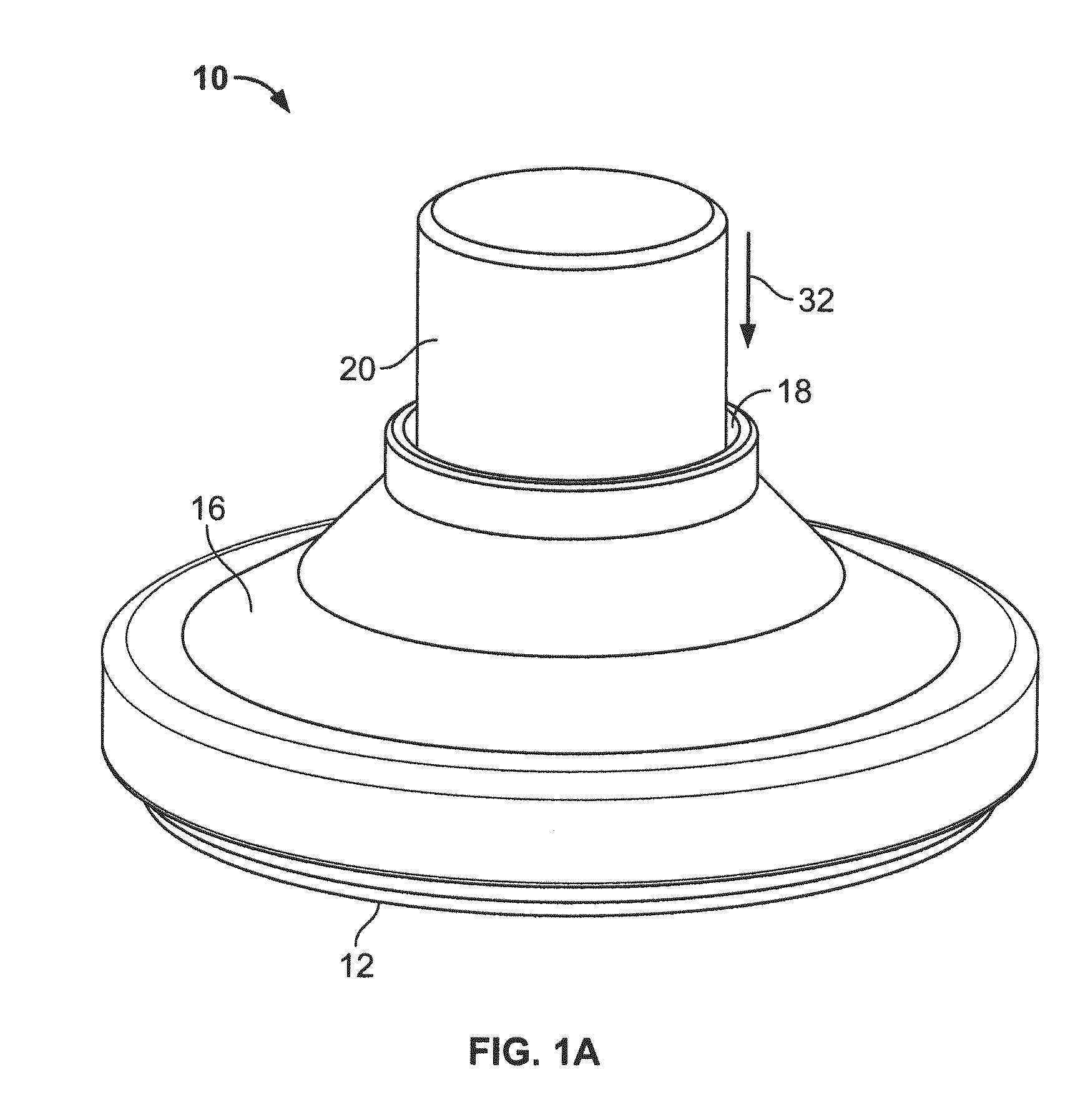
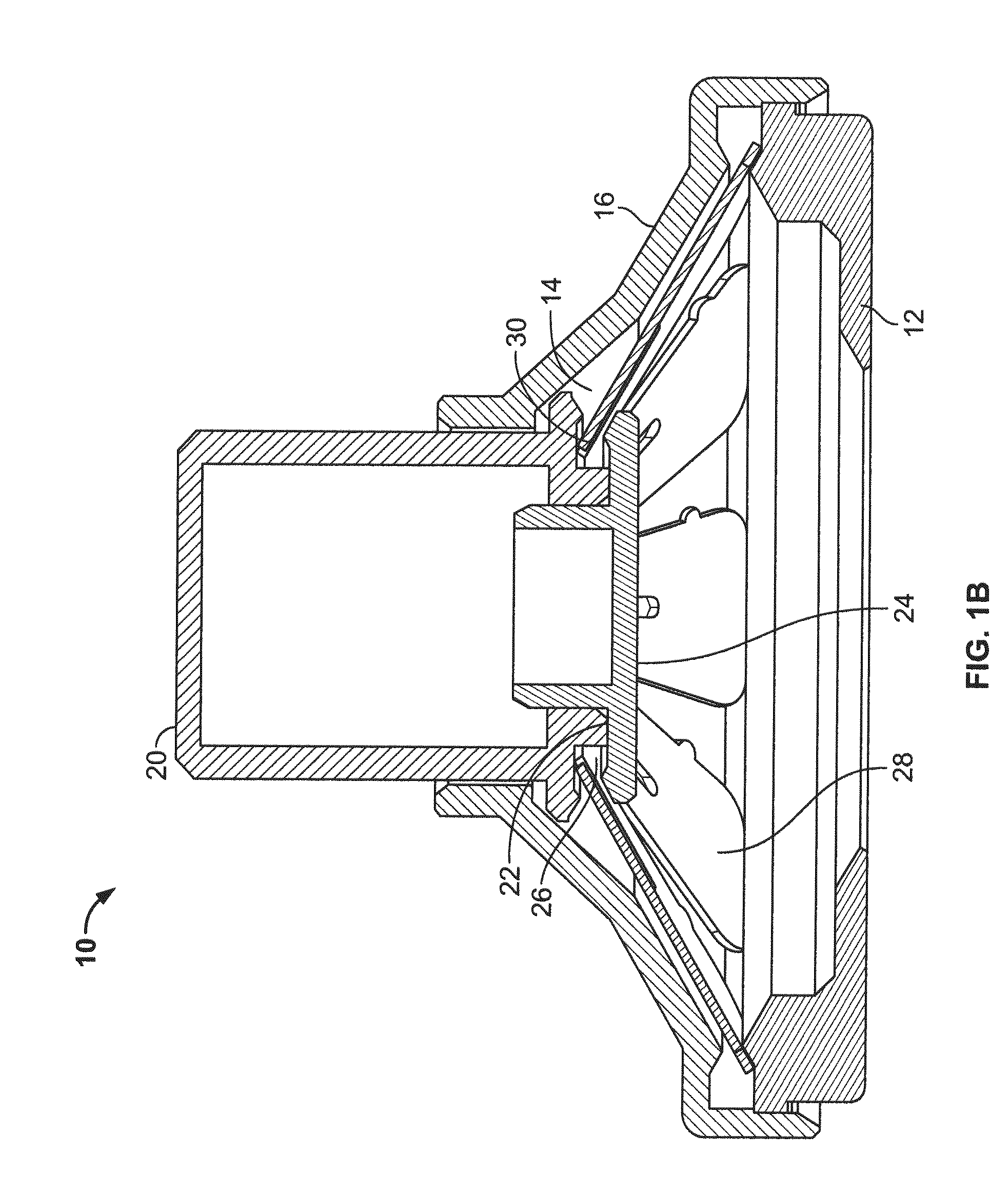
[0116]Three slotted spring applicators designated B1, B2 and B3, similar to those depicted in FIGS. 1A-1F, were compared with an applicator designated “A” of the type depicted in FIGS. 4A-4B for skin penetration efficiency and ability to deliver hPTH(1-34) (human parathyroid hormone 1-34 fragment, also referred to as teriparatide when produced recombinantly). The applicators B1, B2 and B3 differed in the precise characteristics of the slotted spring energy-storing element (dimensions and material). Applicator B1 was 0.012 inches thick stainless steel, Applicator B2 was 0.0155 inches thick and made of 17-7 stainless steel, and Applicator B3 was 0.0155 inches thick and made of 301 stainless steel. The B1 slotted springs had somewhat longer indentations from the outside in comparison to the B2 and B3 slotted springs.

[0117]Microprojection arrays were fabricated from Dextran-70 and containing hPTH(1-34), as described in U.S. Publication No. 2008-0269685....

example 2

Preparation of a Two-Layer Microprojection Array Containing Human Parathyroid Hormone (hPTH(1-34))

[0120]A microprojection array containing a therapeutically effective amount of hPTH(1-34) (32 μgrams) was prepared for use in a Phase I clinical study as follows.

[0121]First, in describing generally the features of the microprojection array, the microprotrusions of the array can be characterized generally as comprising a DIT (drug-in-tip) layer and a “backing” layer. The DIT layer includes hPTH(1-34) in a water-soluble matrix. The sequence of hPTH(1-34) used is as follows:

(SEQ ID NO: 1)H-Ser-Val-Ser-Glu-Ile-Gln-Leu-Met-His-Asn-Leu-Gly-Lys-His-Leu-Asn-Ser-Met-Glu-Arg-Val-Glu-Trp-Leu-Arg-Lys-Lys-Leu-Gln-Asp-Val-His-Asn-Phe-OH

[0122]The tip of the microprojections is also referred to herein as the layer at the bottom-most portion of the tips or microprotrusions (i.e., proximal to the skin when placed upon the skin), also referred to herein as the “end portion” that is distal to the base of ...

example 3

Preparation of a Transdermal Delivery Device (TDS) Containing a Microprojection Array Containing Human Parathyroid Hormone (hPTH(1-34))

[0126]The final transdermal / microneedle delivery system product (sometimes abbreviated herein “TDS”) was assembled and contained the microprojection array described above in Example 2. The product was designed to deliver a systemic dose of hPTH (1-34) across the stratum corneum barrier layer of the skin using an array of microstructures. The final TDS product was formed by the integration of two components, a plunger-array assembly containing drug product and an applicator assembly, where these two items were packaged separately and integrated at the clinical site (See Example 4 below for clinical data).

[0127]The microprojection array contained in the plunger-array assembly possesses an 11 millimeter diameter of approximately 2700 microstructures arranged in a hexagonal pattern. The plunger-array assembly consists of the microprojection array mounted...


PUM


Abstract

An applicator for a microprojection array is described. In one embodiment, the applicator comprises an energy-storing element. Application of force causes the compressed energy-storing element to extend or transition from first and second configurations, releasing stored energy to deploy a holding member in the application which is configured to hold an array of microprojections. In another embodiment, the applicator comprises an energy storing element with two stable configurations, a first stable configuration and second stable configuration. Application of force causes the energy-storing element to transition from the higher energy first stable configuration to the lower energy second stable configuration, releasing the difference in energies of the two states to deploy a holding member in the application which is configured to hold an array of microprojections.

Description

CROSS-REFERENCE TO RELATED APPLICATIONS[0001]This application claims the benefit of U.S. Provisional Application No. 61 / 331,175, filed May 4, 2010, which is incorporated by reference herein.TECHNICAL FIELD[0002]The subject matter described herein relates generally to drug delivery using microneedles or other microprojections, and more specifically to applicators for applying an array of microprojections to the stratum corneum.BACKGROUND[0003]Arrays of microneedles were proposed as a way of administering drugs through the skin in the 1970s, for example in expired U.S. Pat. No. 3,964,482. Microneedle arrays can facilitate the passage of drugs through human skin and other biological membranes in circumstances where ordinary transdermal administration is inadequate. Microneedle arrays can also be used to sample fluids found in the vicinity of a biological membrane such as interstitial fluid, which is then tested for the presence of biomarkers.[0004]In recent years it has become more fea...

Claims


Application Information

Patent Timeline
IPC IPC(8): A61M5/00
CPCA61M37/0015A61B17/205A61M2037/0023A61M37/00A61M5/158
Inventor TRAUTMAN, JOSEPH C.BOURNE, DOUGLAS JOSEPH SCOTTLE, ANTHONYWORSHAM, ROBERT WADESINGH, PARMINDER
Owner CORIUM PHARMA SOLUTIONS INC
Learn More