Supercharged engine system

a supercharged engine and engine technology, applied in the direction of combustion engines, combustion feed systems, combustion air/fuel air treatment, etc., can solve the problems of limiting engine speed, degrading engine balance, and affecting engine performance, so as to prolong the dynamic operating range of the engine and increase the amount of air available to the engine. , the effect of improving engine performan

Inactive Publication Date: 2011-11-17
FORD GLOBAL TECH LLC
View PDF41 Cites 8 Cited by
  • Summary
  • Abstract
  • Description
  • Claims
  • Application Information

AI Technical Summary

Benefits of technology

[0002]Engines may be supercharged to improve engine performance and to extend the dynamic operating range of the engine. Superchargers pressurize air entering the engine by way of a compressor, thereby increasing the amount of air available to the engine. The compressor of a supercharger may be configured with meshing lobes or a centrifugal pump. In U.S. Pat. No. 6,227,179 a supercharger is coupled to engine cylinder heads by way of intake passages that are fed air from an intercooler located downstream of the supercharger. The described supercharger is purported to offer ease of assembly, small packaging, and nimble response. However, bolting a supercharger to the top of an engine may result in alignment issues between the compressor pulley and the engine drive pulley. As such, the compressor may degrade engine balance. Further, coupling the compressor above and away from the engine may limit engine speed since the effective engine inertia is increased by moving the rotating mass away from the crankshaft. Further still, it appears that hoses are required to supply coolant to the intercooler thereby increasing the possibility for developing a coolant leak.

Problems solved by technology

However, bolting a supercharger to the top of an engine may result in alignment issues between the compressor pulley and the engine drive pulley.
As such, the compressor may degrade engine balance.
Further, coupling the compressor above and away from the engine may limit engine speed since the effective engine inertia is increased by moving the rotating mass away from the crankshaft.
Further still, it appears that hoses are required to supply coolant to the intercooler thereby increasing the possibility for developing a coolant leak.
Further, the approach may reduce the possibility of coolant leaks.

Method used


Image

  • Supercharged engine system
  • Supercharged engine system
  • Supercharged engine system

Examples


Embodiment Construction

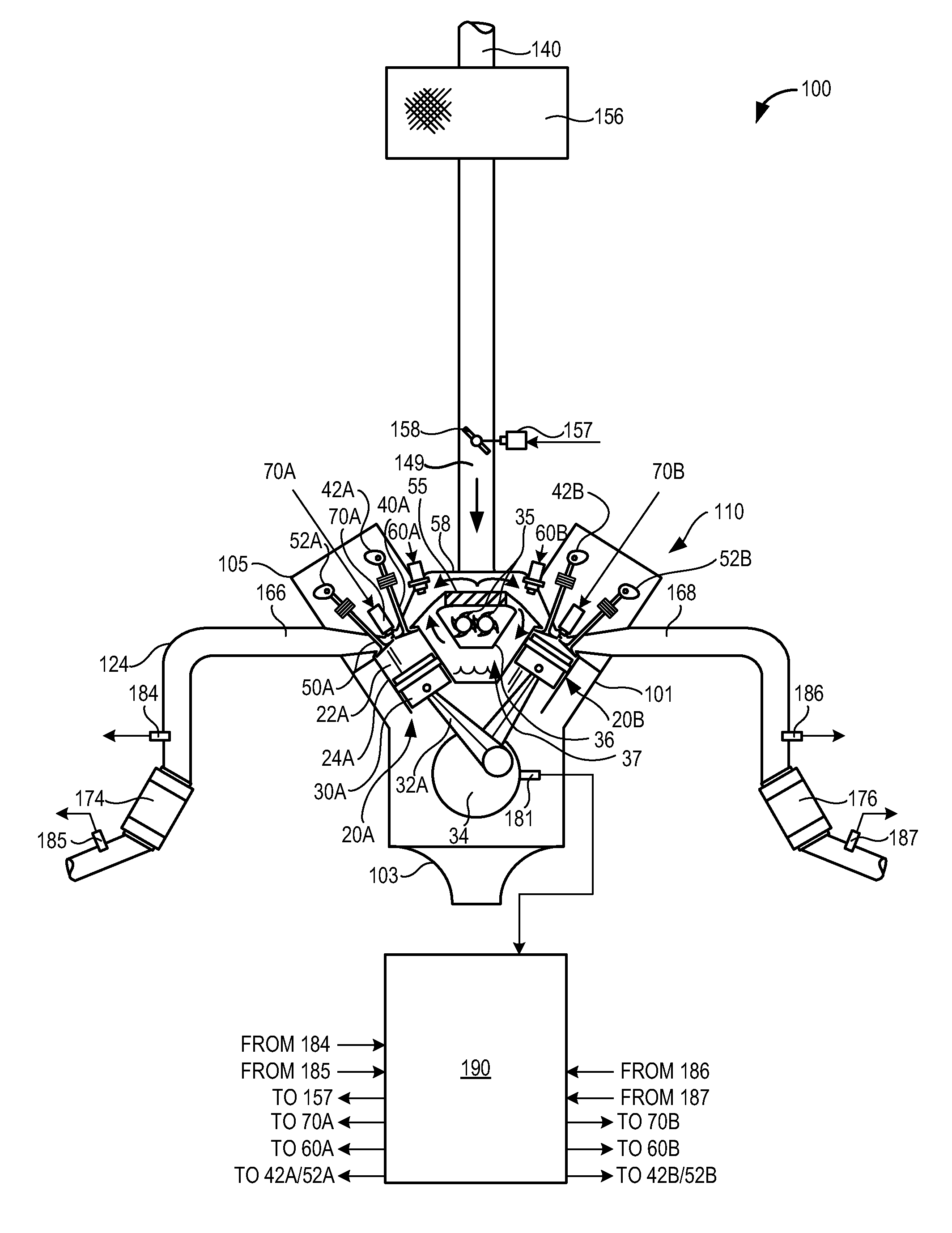
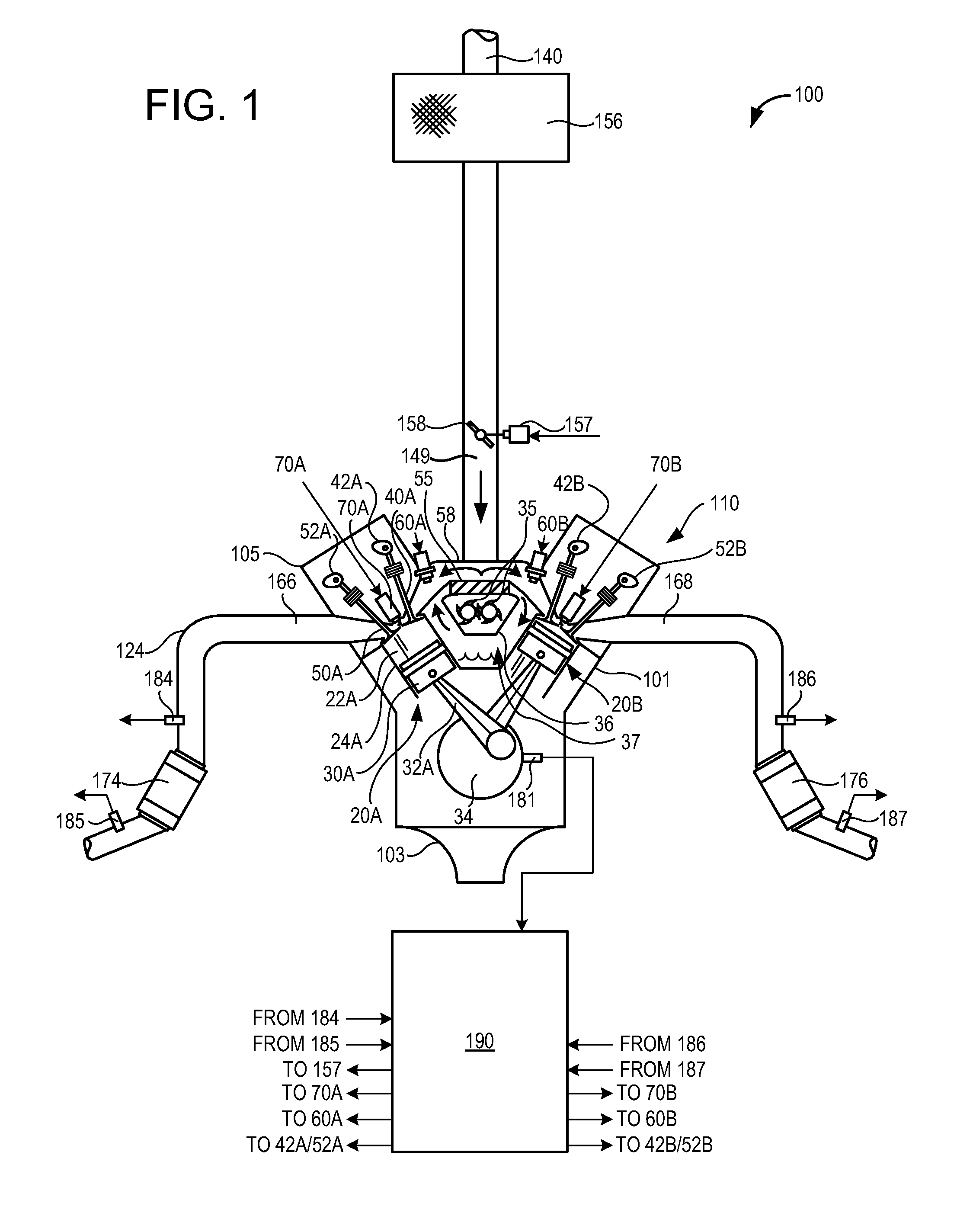
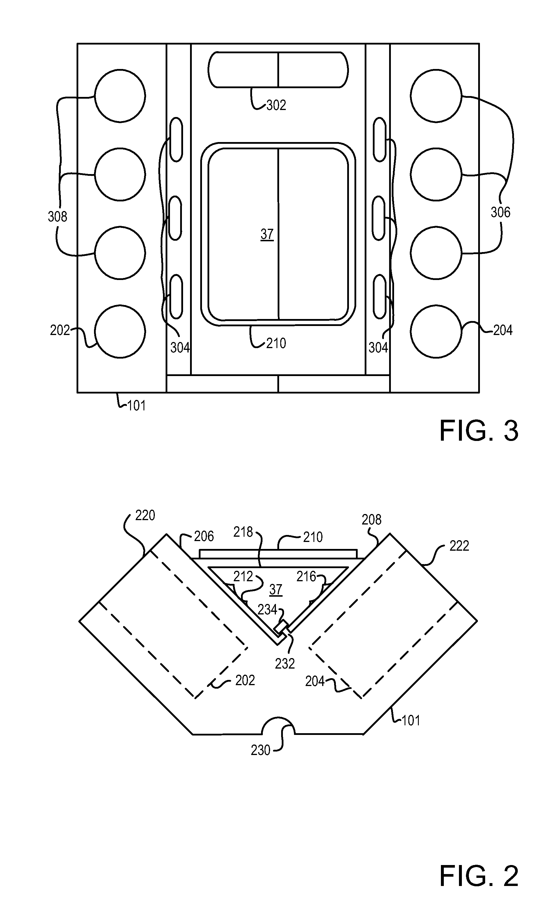
[0018]The present description is related to an engine block with a compressor housing. In one non-limiting example, the engine block may be configured as illustrated in FIGS. 1-3. Further, the compressor may supply compressed air to an intercooler and intake manifold as shown in FIGS. 4-7. Finally, a method for supplying compressed air to an engine block with a compressor housing is described by FIG. 8.

[0019]FIG. 1 shows a schematic depiction of an example engine system 100 including a multi-cylinder internal combustion engine 110 having an integrated compressor housing 36. As one non-limiting example, engine system 100 can be included as part of a propulsion system for a passenger vehicle. Engine system 100 can receive intake air via intake passage 140. Intake passage 140 can include an air filter 156.

[0020]Air travels through intake passage 140 and encounters throttle 149 before entering intake passage 149. In some examples, intake passage 149 may part of engine block 101. Air ent...


PUM


Abstract

A system for supplying compressed air to an engine is presented. In one embodiment, the system includes a cylinder block that forms at least part of an air compressor housing. The system may improve engine balance and reduce engine assembly cost.

Description

FIELD[0001]The present description relates to a system for supplying pressurized air to an internal combustion engine. The system may be useful for improving engine balance and reducing engine assembly costs.BACKGROUND AND SUMMARY[0002]Engines may be supercharged to improve engine performance and to extend the dynamic operating range of the engine. Superchargers pressurize air entering the engine by way of a compressor, thereby increasing the amount of air available to the engine. The compressor of a supercharger may be configured with meshing lobes or a centrifugal pump. In U.S. Pat. No. 6,227,179 a supercharger is coupled to engine cylinder heads by way of intake passages that are fed air from an intercooler located downstream of the supercharger. The described supercharger is purported to offer ease of assembly, small packaging, and nimble response. However, bolting a supercharger to the top of an engine may result in alignment issues between the compressor pulley and the engine ...

Claims


Application Information

Patent Timeline
Patent Type & Authority Applications(United States)
IPC IPC(8): F02B75/22F02B33/00
CPCF02B29/0462F02B29/0475F02B33/36F02B67/10Y02T10/144F02M35/10157F02M35/116Y02T10/146F02B75/22Y02T10/12
Inventor LIIMATTA, GARY DAVID
Owner FORD GLOBAL TECH LLC
Why Eureka
Try Eureka