Through silicon via filling using an electrolyte with a dual state inhibitor

a dual-state inhibitor and silicon via technology, applied in the direction of manufacturing tools, electric circuits, semiconductor/solid-state device details, etc., can solve the problems of difficult deposition of copper into such structures, complex and expensive precursors, limited step coverage, etc., to achieve the effect of improving speed and control

Active Publication Date: 2011-11-24
NOVELLUS SYSTEMS
View PDF6 Cites 95 Cited by
  • Summary
  • Abstract
  • Description
  • Claims
  • Application Information

AI Technical Summary

Benefits of technology

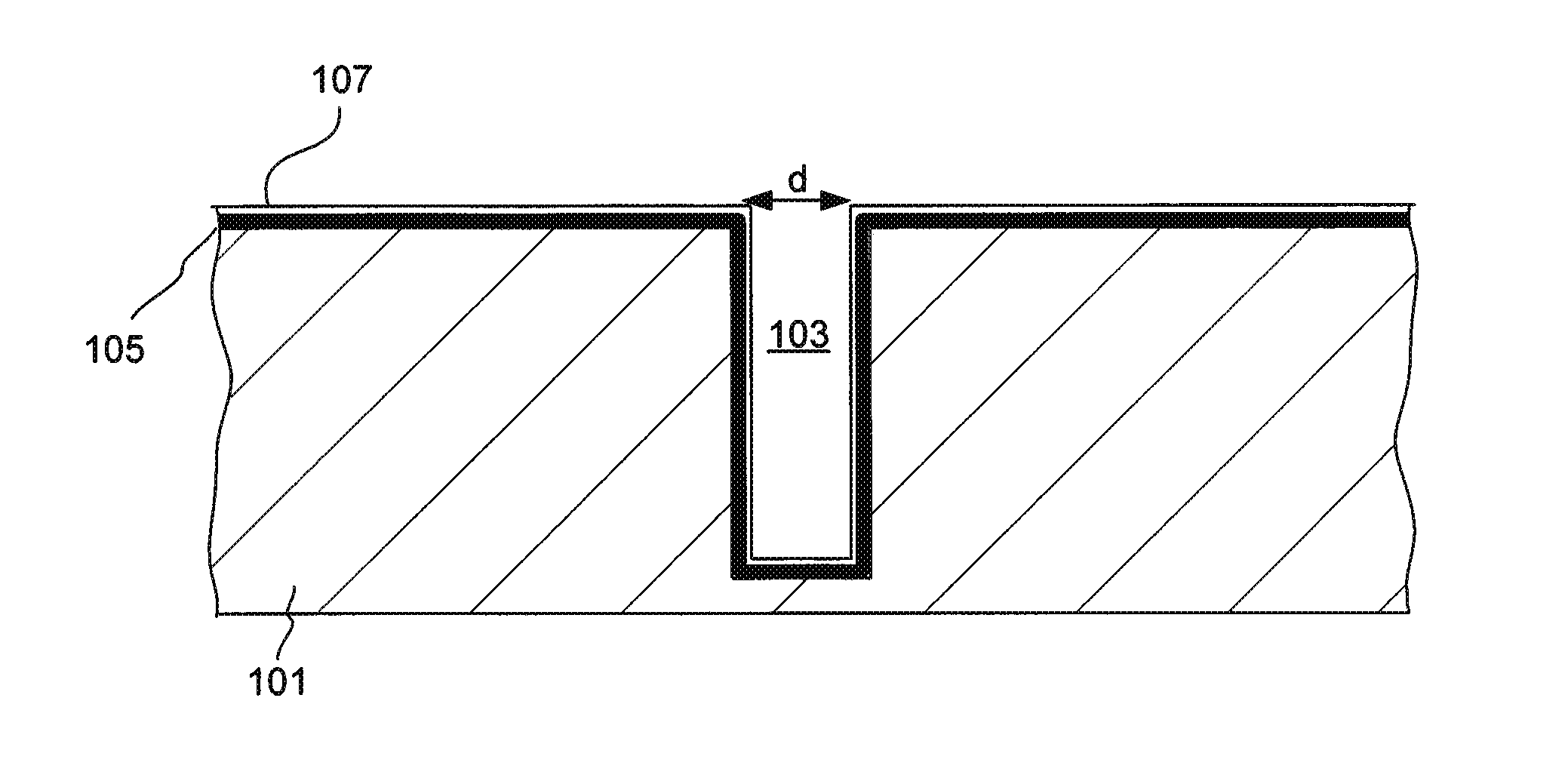
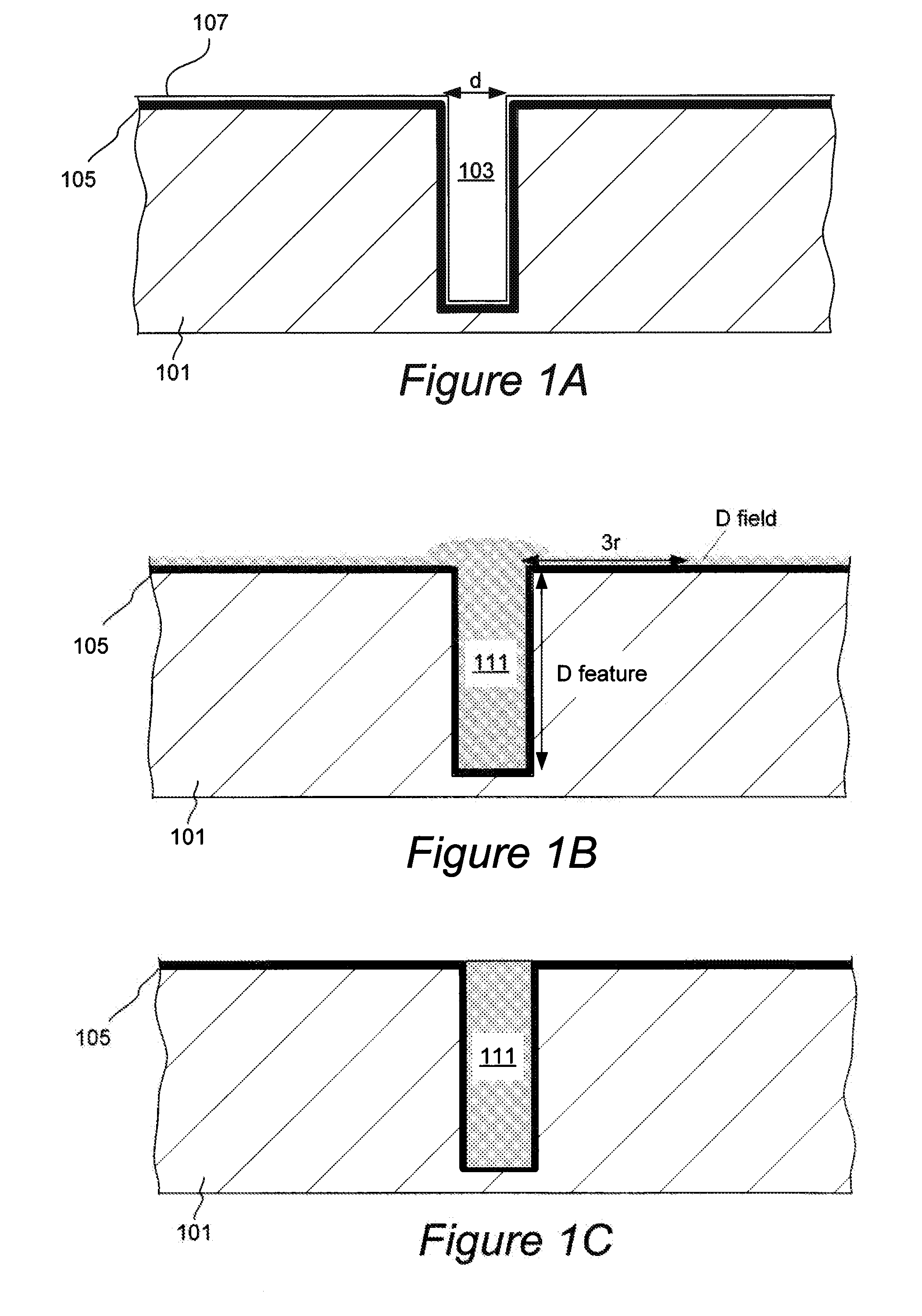
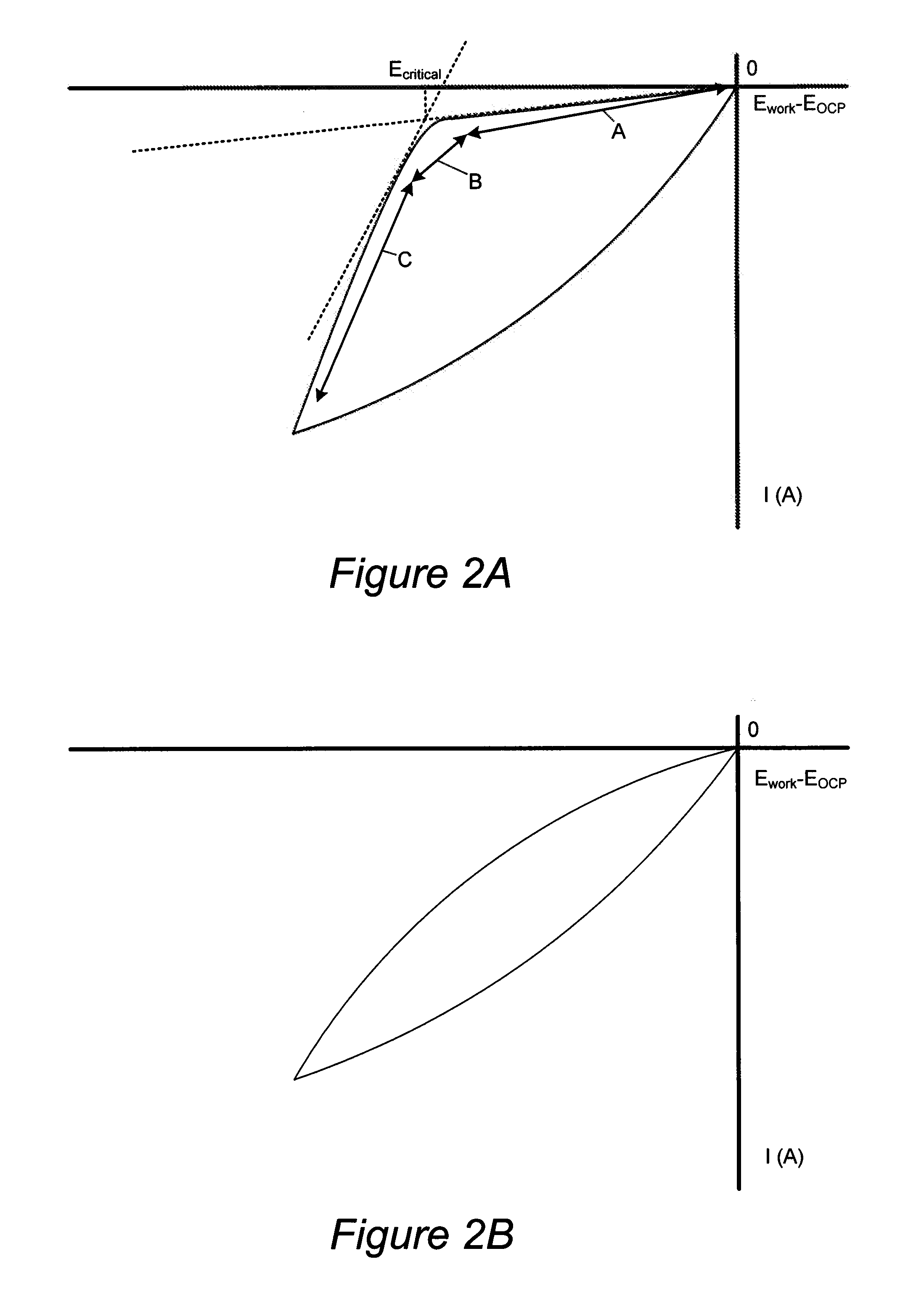
[0011]In the provided methods, electrodeposition in the field region of the substrate is minimized in a controlled manner, by selecting a set of electroplating conditions, which are specifically tailored for a particular type of electroplating bath that uses a dual state inhibitor (DSI) organic additive. DSI additives are organic compounds, which can effectively inhibit deposition of metal over a large range of potential values below a DSI critical potential, resulting in little or no deposition. However, after the critical potential is exceeded, the DSI no longer inhibits electrodeposition, allowing for deposition of metal at fast rates. The presence of DSI additive in the plating bath under a pre-selected set of conditions, allows for fast and efficient bottom-up deposition within the recessed features, without depositing large amounts of metal in the field region.
[0013]In one aspect, a method of electrochemically filling a large, high-aspect ratio recessed feature (such as a TSV having an aspect ratio of at least about 5:1, and a width at the opening of at least about 1 micron) comprises: (a) providing a substrate having a recessed feature (e.g., an array of recessed features) to an electroplating apparatus; and (b) electroplating copper in the recessed feature by contacting the substrate with an electroplating solution comprising (i) copper ions and (ii) an organic DSI compound configured for inhibiting copper deposition in the field region, while electrically biasing the substrate under potential-controlled conditions. The potential (referring to the potential of the metal substrate) is controlled, such that a critical potential of the DSI compound is not exceeded in the field region of the substrate under the used set of plating conditions. As a result, after filling the feature, the ratio of the copper layer thickness deposited on the field to the metal layer thickness deposited in the feature is not greater than about 0.05. Recessed features with aspect ratios of 15:1 and greater can be filled by this method.
[0023]While electroplating can be performed in an absence of acid, in many embodiments the plating solution contains an acid (e.g., sulfuric acid, alkanesulfonic acid or mixtures thereof) to increase the conductivity of the plating solution and to improve the plating rate and within die uniformity. For example, plating solutions containing sulfuric acid and / or methanesulfonic acid at a concentration of at least about 1 g / L, more preferably at least about 10 g / L, such as at least about 40 g / L are used in some embodiments. High acid concentration (0.4 M or more) is preferred in some embodiments, because higher plating rates can be achieved at these concentrations. In some embodiments, sulfuric and / or methanesulfonic acid concentrations of about 100 g / l are used and this has been shown to increase plating rates as well as within die uniformity.

Problems solved by technology

TSV holes typically have high aspect ratios which makes void-free deposition of copper into such structures a challenging task.
CVD deposition of copper requires complex and expensive precursors, while PVD deposition often results in voids and limited step coverage.
Electroplating is a more common method of depositing copper into TSV structures; however, electroplating also presents a set of challenges because of the TSV's large size and high aspect ratio.
However, the use of standard electrolytes and additives often results in very slow plating and in formation of voids during TSV filling.
Further, conformal filling which includes deposition of substantial amounts of copper on the TSV sidewalls, can result in seam voids.
However, this method requires two distinct steps which employ different chemical compounds, and is, therefore, costly.
Additionally, in a two step process, the additional variable of residence time of the substrate between these processes, can cause additional variability in the product, which is undesirable.
Further, in some aspects, provided methods can fill the recessed features with high-purity metal, such that organic additives from electroplating solution are not substantially incorporated into the electrodeposited metal.
However, after the critical potential is exceeded, the DSI no longer inhibits electrodeposition, allowing for deposition of metal at fast rates.
If the critical potential is exceeded, the DSI will stop inhibiting the deposition in the field region which will result in high field deposition thickness and / or formation of voids within the electrofilled features.
If the potential drops to lower values, the electrodeposition within the features may stall or become too slow.

Method used


Image

  • Through silicon via filling using an electrolyte with a dual state inhibitor
  • Through silicon via filling using an electrolyte with a dual state inhibitor
  • Through silicon via filling using an electrolyte with a dual state inhibitor

Examples


example 1

Electroplating with an Electrolyte Containing Thonzonium Bromide DSI

[0124]The preferred plating conditions for a plating electrolyte containing thonzonium bromide, were determined by running a series of CV experiments. The chemical structure of thonzonium bromide is shown below:

[0125]Prior to performing CV experiments, a platinum rotating disk working electrode (RDE) surface was plated with copper from an additive-free electrolyte, containing copper sulfate (at 70 g / L copper ion concentration) and sulfuric acid (at 20 g / L H2SO4 concentration). The exposed electrode surface prior to each CV experiment was a fresh copper surface. Plating of fresh copper layer was performed at a current density of 5 mA / cm2 to deposit about 5000 Å over the 0.1965 cm2 Pt disk electrode. After each CV experiment, all of copper was etched and removed from the Pt RDE, and fresh copper metal was redeposited thereafter prior to subsequent CV test.

[0126]Unless otherwise noted, CV experiments were performed at ...

example 2

Electroplating with an Electrolyte Containing BDHAC DSI

[0136]The preferred plating conditions for a plating electrolyte containing BDHAC, were determined by running a series of CV experiments. The chemical structure of BDHAC is shown below.

[0137]The Pt RDE electrode was prepared for CV experiments, in the same manner as was described in Example 1. The sweep rate and reference electrode used in CV experiments were the same as used in Example 1.

[0138]The electrolytes used in CV experiments contained copper sulfate (20-70 g / L Cu1+), sulfuric acid (0-100 g / L H2SO4), BDHAC (5-50 ppm) and, optionally, HCl as a source of chloride additive (0-50 ppm). The rotation rate of the electrode was varied from 30 to 120 ppm.

[0139]It was determined by obtained CV curves, that BDHAC maintains good DSI switching behavior at low-acid concentrations, but loses its switching behavior at high acid concentrations (at 100 g / L H2SO4 and above). While not being bound by the particular theory, it is believed th...

example 3

Electroplating with an Electrolyte Containing DVF 200 C

[0147]The preferred plating conditions for a plating electrolyte containing DVF 200 C, were determined by running a series of CV experiments.

[0148]The Pt RDE electrode was prepared for CV experiments, in the same manner as was described in Example 1.

[0149]The electrolytes used in CV experiments contained copper sulfate (20-70 g / L Cu2+), sulfuric acid (20-100 g / L), DVF 200 C (5-30 mL / L) and, optionally, HCl as a source of chloride additive (0-50 ppm). The rotation rate of the electrode was varied from 30 to 120 ppm.

[0150]It was determined by obtained CV curves, that DVF 200 C maintains good DSI switching behavior only at relatively high concentrations of DVF 200 C, but loses its switching behavior at low additive concentrations.

[0151]Exemplary conditions determined to be suitable are as follows: copper sulfate (50-70 g / L Cu2+), sulfuric acid (20-100 g / L), DVF 200 C (10-20 mL / L) and, optionally, HCl as a source of chloride additiv...


PUM

PropertyMeasurementUnit
widthaaaaaaaaaa
concentrationaaaaaaaaaa
diameteraaaaaaaaaa

Abstract

A method for electrofilling large, high aspect ratio recessed features with copper without depositing substantial amounts of copper in the field region is provided. The method allows completely filling recessed features having aspect ratios of at least about 5:1 such as at least about 10:1, and widths of at least about 1 μm in a substantially void-free manner without depositing more than 5% of copper in the field region (relative to the thickness deposited in the recessed feature). The method involves contacting the substrate having one or more large, high aspect ratio recessed features (such as a TSVs) with an electrolyte comprising copper ions and an organic dual state inhibitor (DSI) configured for inhibiting copper deposition in the field region, and electrodepositing copper under potential-controlled conditions, where the potential is controlled not exceed the critical potential of the DSI.

Description

CROSS-REFERENCE TO RELATED APPLICATIONS[0001]This application claims priority under 35 USC 119(e) from U.S. Provisional Patent Application No. 61 / 346,350 naming Willey and Mayer as inventors, titled “Through Silicon Via Filling Using an Electrolyte With a Dual State Inhibitor” filed May 19, 2010, and from U.S. Provisional Patent Application No. 61 / 439,111 naming Willey and Mayer as inventors, titled “Through Silicon Via Filling Using an Electrolyte With a Dual State Inhibitor” filed Feb. 3, 2011, which are herein incorporated by reference for all purposes.FIELD OF THE INVENTION[0002]The present invention relates generally to methods and apparatus for electrodepositing metals on substrates having recessed features and more particularly to methods and apparatus for electroplating copper for filling through silicon vias (TSVs).BACKGROUND OF THE INVENTION[0003]A TSV is a vertical electrical connection passing completely through a silicon wafer or die. TSV technology is important in crea...

Claims


Application Information

Patent Timeline
Patent Type & Authority Applications(United States)
IPC IPC(8): C25D5/02C25D19/00C25D3/38
CPCC25D3/38H01L21/2885C25D5/022C25D7/123H01L21/76898H01L2924/0002H01L2924/00C25D21/12H01L21/76879H01L23/53228
Inventor WILLEY, MARK J.MAYER, STEVEN T.
Owner NOVELLUS SYSTEMS
Why Eureka
Try Eureka