
High Concentration NO2 Generating System and Method for Generating High Concentration NO2 Using the Generating System

a generating system and high concentration technology, applied in the direction of nitrogen oxides, nitrogen oxides/oxyacids, nitrogen dioxide, etc., can solve the problem that the method cannot be used for the purpose of high sterilization level, and achieve the effect of high sterilization

Active Publication Date: 2011-11-24
NOXILIZER
View PDF4 Cites 9 Cited by
  • Summary
  • Abstract
  • Description
  • Claims
  • Application Information

AI Technical Summary

Benefits of technology

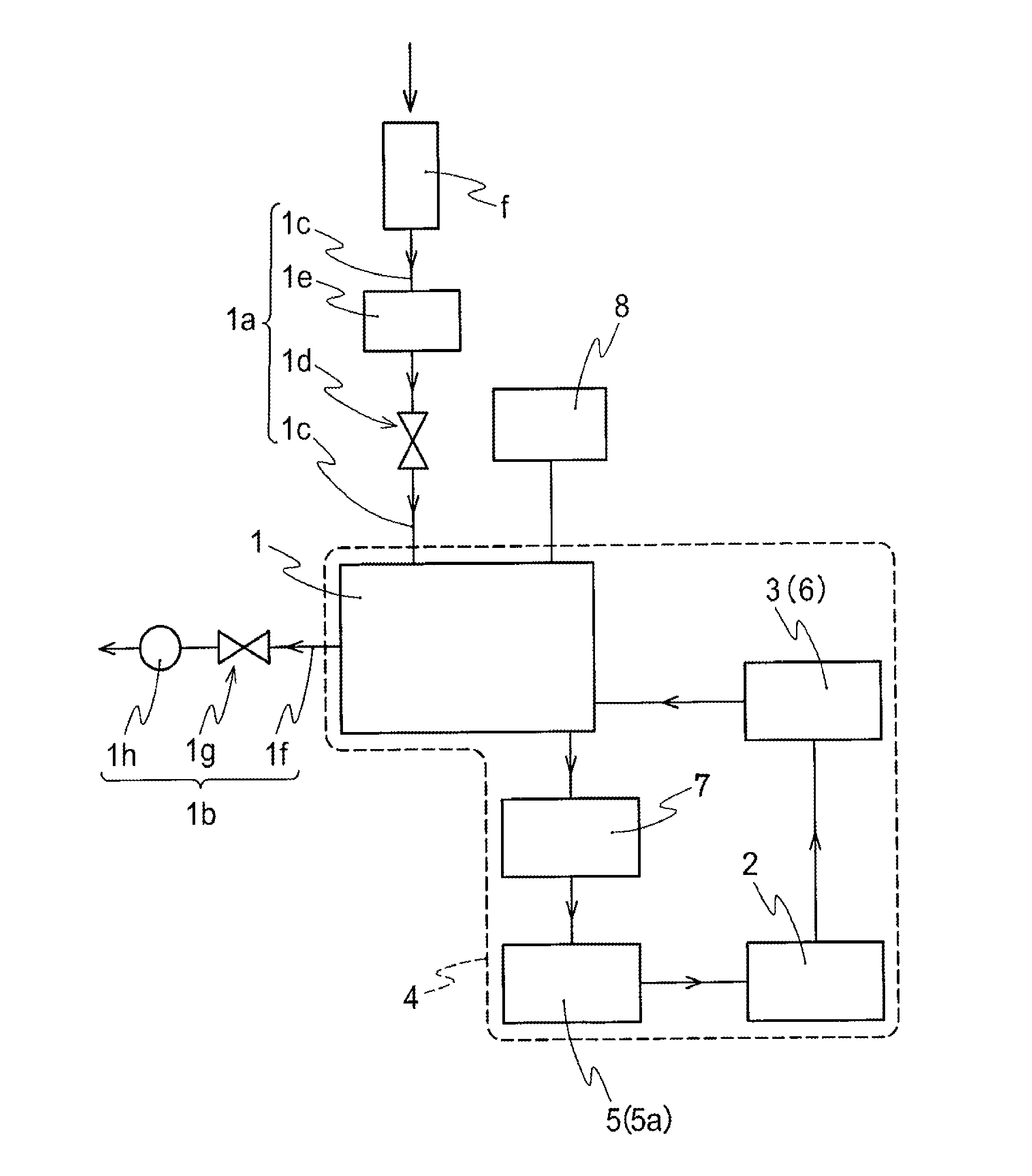
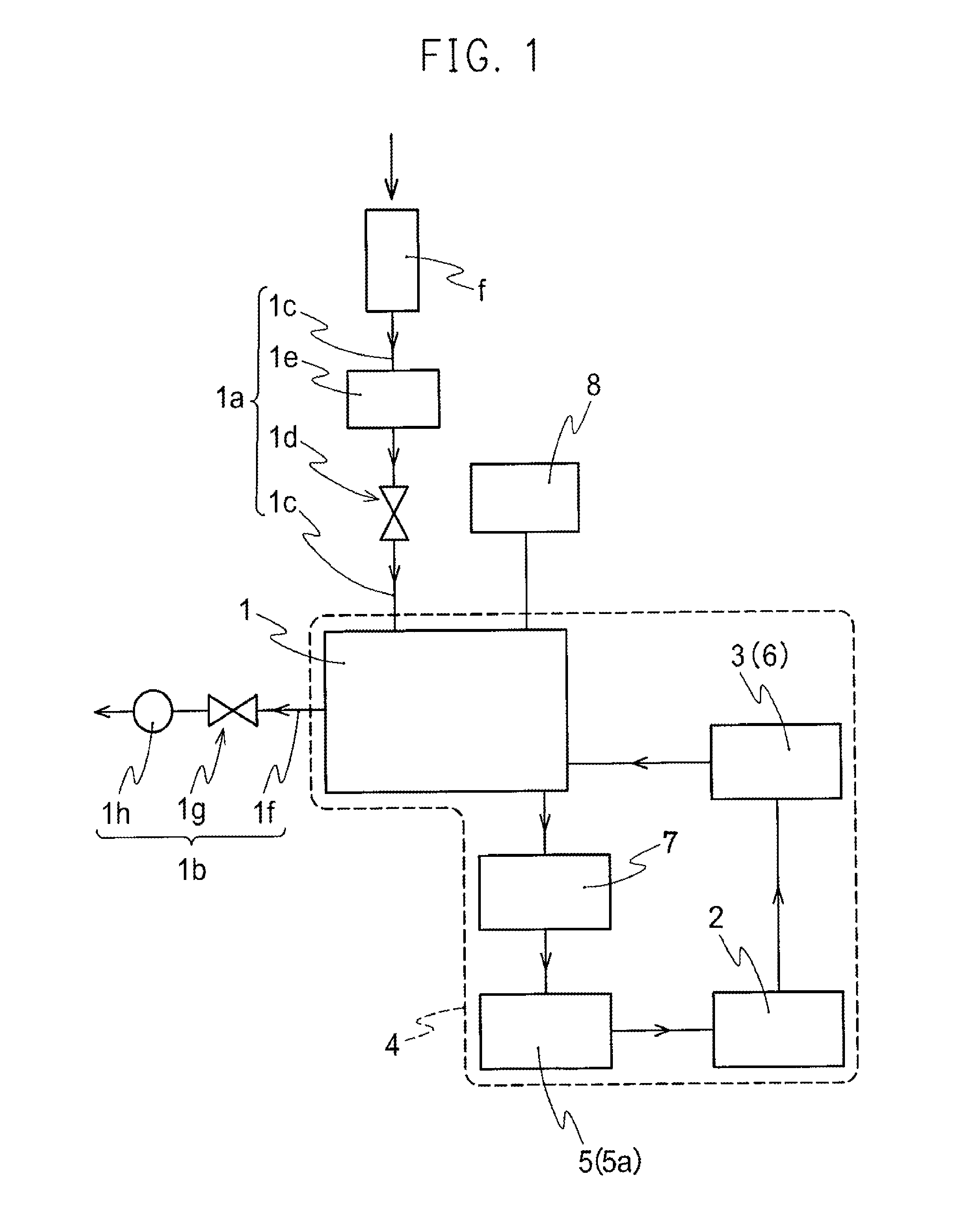
"The present invention provides a high concentration NO2 generating system and a method for generating high concentration NO2 using the generating system. The system includes a chamber, NO2 sensor, flow resistor, flow meter, plasma generator, pressure meter, circulating pump, dry air supply apparatus, and exhaust pump. The system can generate high concentration NO2 quickly and selectively for high level sterilization processes such as sterilizing medical instruments. The method involves circulating an NOx gas mixture in a circulating path formed by a chamber, a plasma generator, and a circulating means until NO2 concentration reaches 500 ppm to 100,000 ppm. The gas mixture can be made of ambient air or dry air with a dew point from 0 to -90° C. The system is compact and can maintain an internal pressure of the interval from the pressure device through the chamber to the flow resistive portion connected to the chamber at a positive pressure relative to atmospheric pressure. The flow volume of the NOx gas mixture circulating in the circulating path is 5LPM or above."

Problems solved by technology

Accordingly, there is a problem that the method can never be used for the purpose of a high level of sterilization where enhanced reliability is desired (for example, medical instruments attached with germs; more specifically, sterilization of a microspace such as between scissors and an inside of a tube).

Method used


Image

  • High Concentration NO2 Generating System and Method for Generating High Concentration NO2 Using the Generating System
  • High Concentration NO2 Generating System and Method for Generating High Concentration NO2 Using the Generating System
  • High Concentration NO2 Generating System and Method for Generating High Concentration NO2 Using the Generating System

Examples


example 1

[0092]In the circulating path shown in FIG. 4, when the internal pressure of the chamber 1 was vacuum (−101 kPa (relative pressure)), the air (dew point −60° C.) was filled such that the internal pressure of the chamber 1 was to be −5 kPa (relative pressure). The air was made to circulate by a pressure device 61 and pressure device 62, and a flow resistive portion 51 and flow resistive portion 52 were adjusted such that the flow meter F1 and flow meter F2 indicated 16 LPM. The pressure in the circulating path at this time was monitored to be from 60 to 70 kPa (absolute pressure) with a pressure meter PG1 and pressure meter PG2. With a plasma generator 21 and plasma generator 22, two electrodes were inserted in the waveguide 2b to apply 160 W of electric power to the plasma generator 21 and plasma generator 22. The concentration of the high concentration NO2 gas was measured over time by the NO2 concentration measuring means 7. The result is shown in FIG. 5. The reference numeral E1 ...

example 2

[0093]Two electrodes were inserted in the plasma generator 21 to apply 160 W of electric power. Electric power was not applied to the other plasma generator 22. Other arrangement was the same as that of Example 1, and the concentration of the high concentration NO2 gas was measured over time. The result is shown in FIG. 5. The reference numeral E2 is a graph showing the changes of the concentration of the high concentration NO2 gas over time according to Example 2.

example 3

[0094]One electrode was inserted in the plasma generator 21 to apply 80 W of electric power. Electric power was not applied to the other plasma generator 22. Other arrangement was the same as that of Example 1, and the concentration of the high concentration NO2 gas was measured over time. The result is shown in FIG. 5. The reference numeral E3 is a graph showing the changes of the concentration of the high concentration NO2 gas over time according to Example 3.

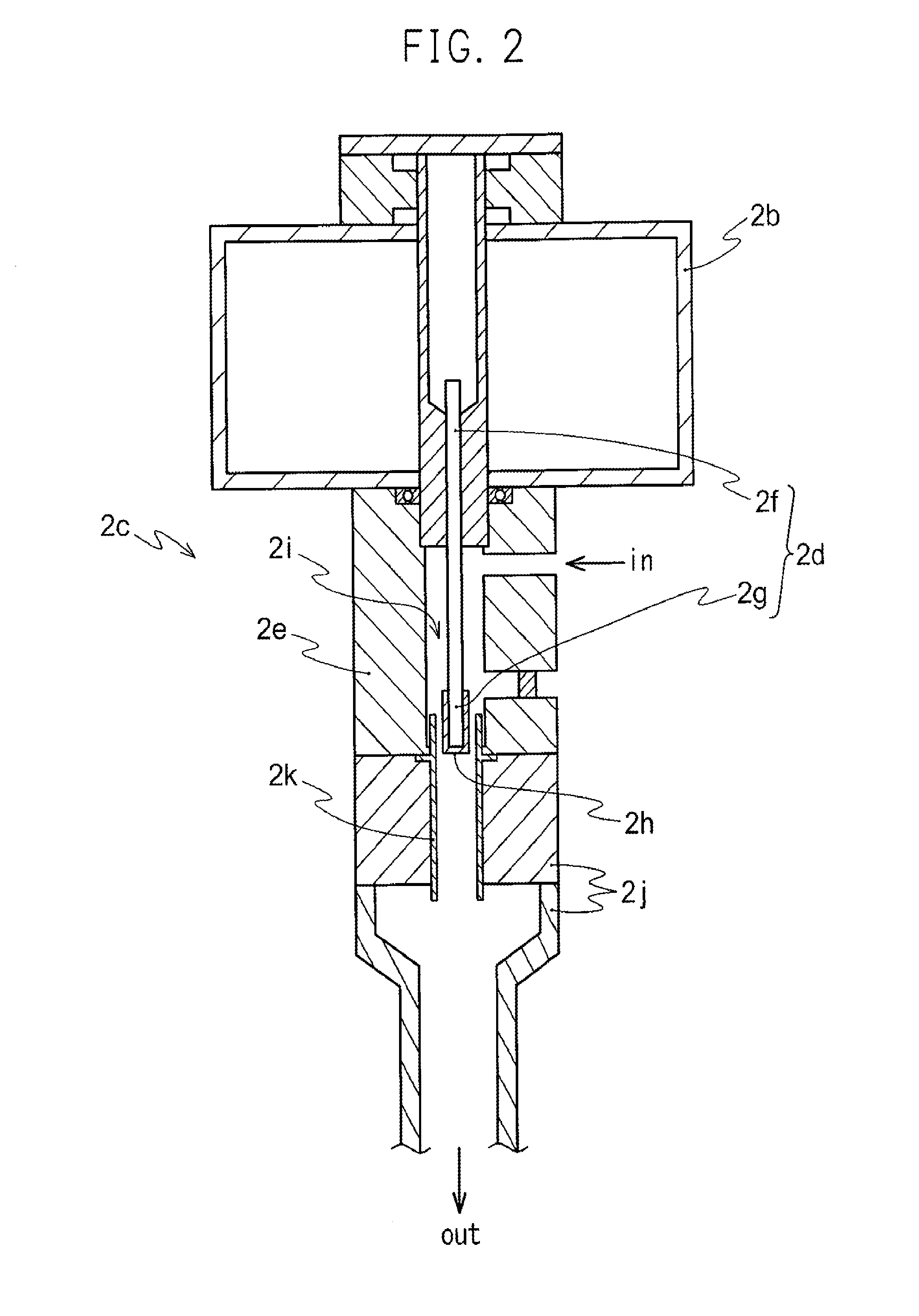
[0095]From Examples 1 to 3, it was found that the increase in the concentration of the high concentration NO2 is faster when the number of the electrodes (conducting shaft 2d) is increased. The concentration reached 70 mg / L in approximately 60 minutes in Example 1, the concentration reached 70 mg / L in approximately 120 minutes in Example 2, and the concentration reached 70 mg / L in approximately 240 minutes in Example 3. Therefore, it was found that the number of electrodes (conducting shaft 2d) is proportional to the generati...


PUM

PropertyMeasurementUnit
relative pressureaaaaaaaaaa
temperatureaaaaaaaaaa

Abstract

A high concentration NO2 gas generating system including a circulating path configured by connecting a chamber, a plasma generator, and a circulating means, wherein NO2 is generated by circulating a gas mixture including nitrogen and oxygen in the circulating path is provided. The high concentration NO2 gas generating system provides a high concentration NO2 generating system and the high concentration NO2 generating method using the generating system by which NO2 of high concentration (approximately 500 ppm or above) required for a high level of sterilization process in such as sterilization of medical instruments can be simply and selectively obtained. In addition, since indoor air is used as an ingredient, the management of ingredients is simple and highly safe, and the high concentration of NO2 can be simply and selectively prepared on demand.

Description

TECHNICAL FIELD[0001]The present invention relates to a high concentration NO2 generating system and a method for generating high concentration NO2 using the generating system. More particularly, the present invention relates to a high concentration NO2 generating system for obtaining NO2 of high concentration in a simple and selective manner by using the air as an ingredient, and a method for generating a high concentration NO2 using the generating system.BACKGROUND ART[0002]Conventionally, as sterilizing methods of medical instruments, high-pressure steam sterilization (hereinafter, simply referred to as “AC”) and ethylene oxide gas sterilization (hereinafter, simply referred to as “EOG sterilization”) have been widely used.[0003]AC is a sterilization method in which an item to be sterilized is exposed under a high temperature at approximately 135° C., and has been widely used for medical instruments made of metal. However, there is a disadvantage that limitations exist in items t...

Claims


Application Information

Patent Timeline
Patent Type & Authority Applications(United States)
IPC IPC(8): C01B21/36B01J19/08
CPCA61K33/00B82Y30/00C01B21/36B01J19/088B01J19/126H05H2001/4622B01J2219/0883B01J2219/0896H05H1/46H05H1/4622
Inventor MATSUUCHI, HIDETAKAHIROSE, TOMOYUKIIWASAKI, RYUICHIMIKE, MASAAKIMASUDA, SHIGERUHAYASHI, HIROFUMITANIBATA, TORUKIM, JOONGSOOLEE, SANG HUNKOO, JAE-MOWEIHE, ORIONWAY, ANDREW
Owner NOXILIZER
Learn More