Fiber-Hydrogel Composite for Tissue Replacement

a fiber-hydrogel and tissue technology, applied in the direction of prosthesis, ligaments, impression caps, etc., can solve the problems of meniscus not being able to withstand the mechanical burden placed on, affecting the healing effect of the meniscus, and affecting the healing effect of the bone marrow, so as to achieve the effect of minimizing the swelling of the composi

Inactive Publication Date: 2011-11-24
DREXEL UNIV +1
View PDF9 Cites 21 Cited by
  • Summary
  • Abstract
  • Description
  • Claims
  • Application Information

AI Technical Summary

Benefits of technology

[0012]The present invention also relates to a method of controlling the mechanical properties of a fiber-reinforced hydrogel composite that mimics a native tissue of a mammal and is suitable for implantation in the mammal. The method includes the steps of selecting at least one fibrous componen

Problems solved by technology

Sometimes the meniscus cannot withstand the mechanical burdens placed upon it, and it tears.
Unfortunately, the deleterious effects of meniscectomy include limited mobility, pain and ultimately osteoarthritic degradation (Allen, et al., 1984, J Bone Joint Surg Br 66-B:666-671; Fairbank, 1948, J Bone Joint Surg Am.
30B:664-670; Johnson, et al., 1974, Journal of Bone and Joint Surgery—American 56A: 719-729), and the subsequent deterioration of the joint leads to disability, the need for multiple surgeries, and oftentimes total knee joint replacement.
With such a prevalence of meniscal degeneration, a meniscectomy that leads directly to late-stage osteoarthritis and total knee replacement is an undesirable treatment option.
However, providing a meniscal substitution could delay or even avoid the onset of osteoarthritis.
Unfortunately, each of these options has significant drawbacks.
However, problems with allografts include transmission of infectious diseases and the difficulty of matching the donor meniscal shape to that of the recipient.
Autografts are tendon/ligament/fat pad grafts that are transplanted from a remote location into the knee joint, but these have produced disappointing results in the mid- to long-term (Goble, et al., 1999, Scand J Med Sci Sports.
Bioresorbable scaffolds are designed to encourage tissue ingress while gradually resorbing, but the ability of bioresorbable scaffolds to carry joint contact loads is questionable, and there is little mechanical test data to support their use, as few have been tested in the joints of large weight bearing animals.
However, the tensile properties of hydrogels a

Method used


Image

  • Fiber-Hydrogel Composite for Tissue Replacement
  • Fiber-Hydrogel Composite for Tissue Replacement
  • Fiber-Hydrogel Composite for Tissue Replacement

Examples


examples

[0067]The invention is now described with reference to the following Examples. These Examples are provided for the purpose of illustration only, and the invention is not limited to these Examples, but rather encompasses all variations that are evident as a result of the teachings provided herein.

[0068]The materials and methods employed in the experiments and examples disclosed herein are now described.

PVA Hydrogel Synthesis

[0069]PVA (99+% hydrolyzed), with a molecular weight of about 89,000-98,000 g / mol, and poly(vinyl pyrrolidone) (PVP), with a molecular weight of about 40,000 g / mol, were obtained from Sigma Aldrich. PVP was added in small amounts to the hydrogel formulation to improve network stability through interchain hydrogen bonding [Thomas et al., 2003, J Biomed Mater Res A. 67(4):1329-37]. Polymer solutions were prepared by mixing about 10 to 20 wt % polymer, composed of approximately 99 wt % PVA and 1 wt % PVP, in deionized water. The container was sealed and autoclaved at...

example # 1

Example #1

PVA Hydrogel

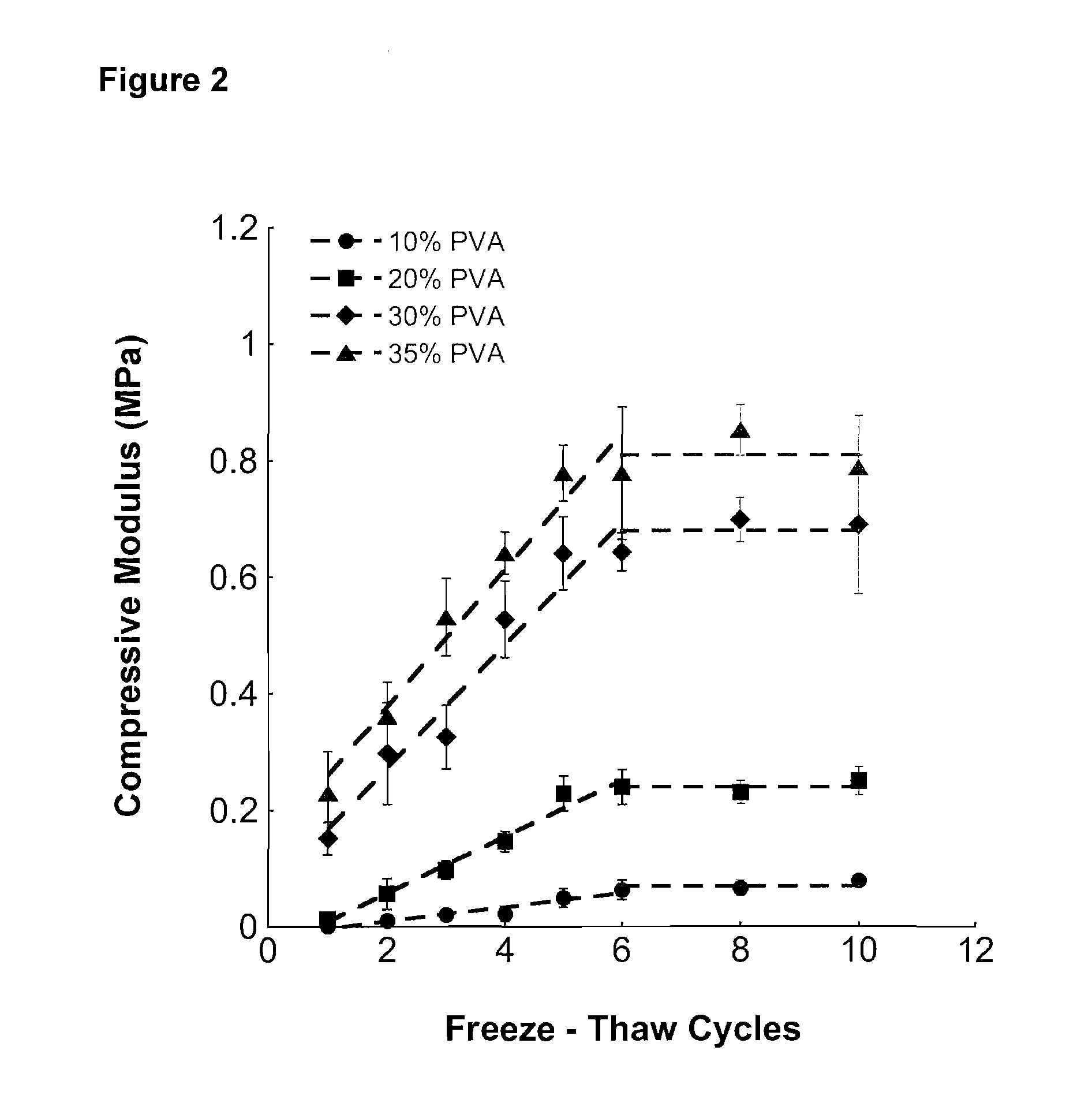
[0083]Compressive and tensile testing was performed on PVA hydrogels synthesized from one to ten freeze-thaw cycles. As depicted in FIG. 2, compressive modulus values were calculated as the average slope of the stress-strain curves between 1% and 5% strain. For all PVA concentrations, linear trends in modulus were observed through the first six freeze-thaw cycles. After six cycles, the compressive modulus did not increase significantly (p<0.05), and reached a plateau value. Also depicted in FIG. 2 are trend lines representing the best fit through the first six freeze-thaw cycles and the average modulus within the plateau region. Polymer concentration had a significant effect on compression modulus (p<0.05). Notably, the compressive modulus for 20 wt % PVA is within the range of the native meniscus, which has an aggregate compressive modulus of 0.22 MPa [Almarza et al., 2004, Ann Biomed Eng. 32(1):2-17].

[0084]Tensile modulus values were also calculated as the av...

example 2

Fiber Reinforced PVA Composite

[0089]Tensile testing was performed on PVA hydrogels reinforced with polypropylene and UHMWPE fibers. Tensile modulus values were calculated from the average slope of the linear region in the stress versus strain curve. Depicted in FIGS. 7 and 8 are plots of tensile modulus as a function of fiber volume fraction (Vf) for polypropylene and UHMWPE fiber-reinforced hydrogels, respectively. Linear increases in modulus as a function of fiber volume fraction were observed in both cases, for the range of Vf examined. PP-PVA composites showed an increase in modulus from about 0.23±0.02 MPa for neat PVA to about 8.2±0.6 MPa at 10% Vf polypropylene. Reinforcement with UHMWPE fabrics resulted in a tensile modulus of about 90.6±21.6 MPa to 258.1±40.1 MPa at volume fractions of approximately 10% and 29% UHMWPE, respectively. UHMWPE-PVA composites exhibited similar tensile stiffness to that seen in the native meniscus in the circumferential direction, which is about ...


PUM


Abstract

The present invention includes tailored fiber-reinforced hydrogel composites for implantation into a subject. The present invention also includes systems and methods for controlling the relative percent volume of the hydrogel and fibers, cross-linking, fiber orientation, weave and density, such that the material properties of the composite can be controlled and/or customized to match particular tissue types. The composites of the present invention are suitable for repairing or replacing musculoskeletal tissues and/or fibrocartilage, such as the meniscus, ligaments and tendons.

Description

STATEMENT REGARDING FEDERALLY SPONSORED RESEARCH OR DEVELOPMENT[0001]This invention was made with support from the U.S. Department of Defense through the National Defense Science and Engineering Graduate Fellowship, in addition to the U.S. Army Research Laboratory through the Army Materials Center of Excellence Program, contract W911NF-06-2-0013. The government has certain rights in the invention.BACKGROUND OF THE INVENTION[0002]The menisci are C-shaped fibrocartilage disks with a cross-sectional wedge-shape that occupy the periphery of the knee joint, as depicted in prior art FIG. 1. The anterior and posterior horns of the menisci are connected to the tibial plateau by ligaments that insert into the intercondylar regions. During loading, radial (extrusive) forces are resisted by these firm attachments, particularly to the tibia at the anterior and posterior horns. This produces large circumferentially oriented hoop tensile stresses within the meniscus.[0003]Sometimes the meniscus c...

Claims


Application Information

Patent Timeline
IPC IPC(8): A61L27/48A61F2/44A61F2/38A61F2/08A61F2/02A61F2/28
CPCA61F2/30965A61L27/48A61F2/3872
Inventor LOWMAN, ANTHONY M.PALMESE, GIUSEPPE R.MAHER, SUZANNE A.WARREN, RUSSELL F.WRIGHT, TIMOTHY M.HOLLOWAY, JULIANNE L.
Owner DREXEL UNIV
Why Eureka
Try Eureka