Oscillator circuit

a technology of oscillator circuit and oscillator, which is applied in the direction of oscillator generator, pulse automatic control, pulse technique, etc., can solve the problems of increasing current consumption, deteriorating oscillation startup characteristics, and more noticeable disadvantages, so as to improve the start-up characteristics of quick oscillation startup, stable oscillation, and reduce current consumption

Active Publication Date: 2011-12-01
PANASONIC SEMICON SOLUTIONS CO LTD
View PDF3 Cites 29 Cited by
  • Summary
  • Abstract
  • Description
  • Claims
  • Application Information

AI Technical Summary

Benefits of technology

[0034]The present invention is technically characterized in that the performance of the performance-variable inverter is regulated in the initial phase of oscillation startup where the ON / OFF inverter and the performance-variable inverter are both operational. The advantages obtained by the technical characteristic are; an overall inverter performance suitably regulated is exerted so that startup characteristics (quick oscillation startup) are improved, while at the same time an abnormal oscillation resulting from over-performance is prevented from happening and current consumption is reduced, and the oscillation is reliably stabilized by increasing the performance of the performance-variable inverter in the post-startup phase where the ON / OFF inverter is disconnected for noise reduction.

Problems solved by technology

In an IC-chip circuitry system, a constant of equivalent series impedance is becoming smaller as a piezoelectric vibrator is increasingly miniaturized, often deteriorating oscillation startup characteristics.
These disadvantages are more noticeable particularly in the technical fields relevant to smart meter-based remote monitoring, automated meter readers, and security systems such as radio-equipped security and disaster control devices.
However, such a large driving performance leads to an increase of current consumption at the same time, failing to meet the demand for improvement of a battery life.

Method used


Image

  • Oscillator circuit
  • Oscillator circuit
  • Oscillator circuit

Examples


exemplary embodiment 1

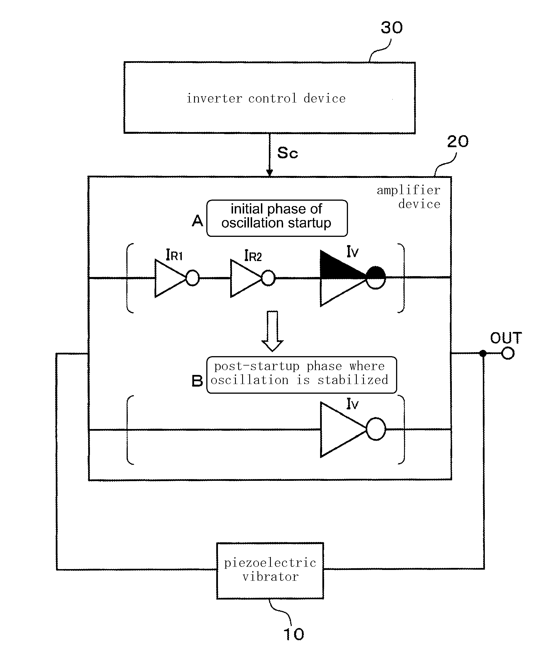
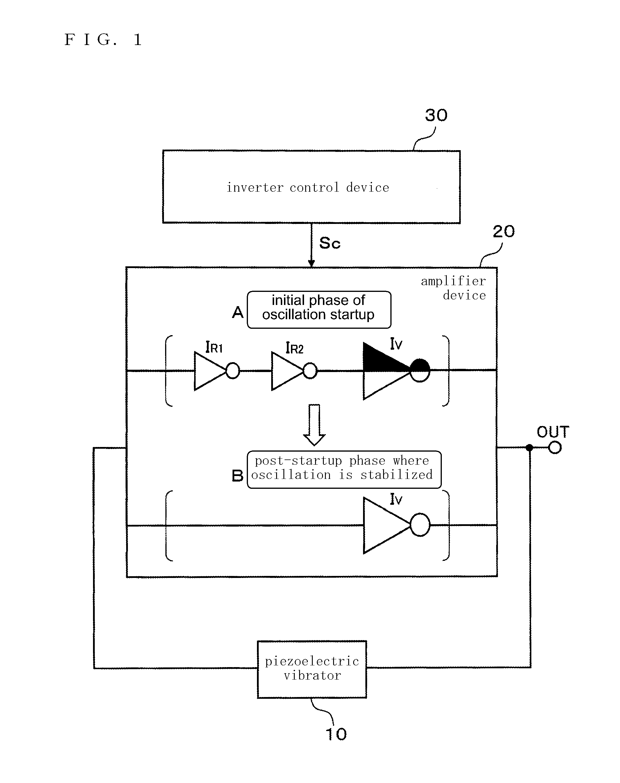
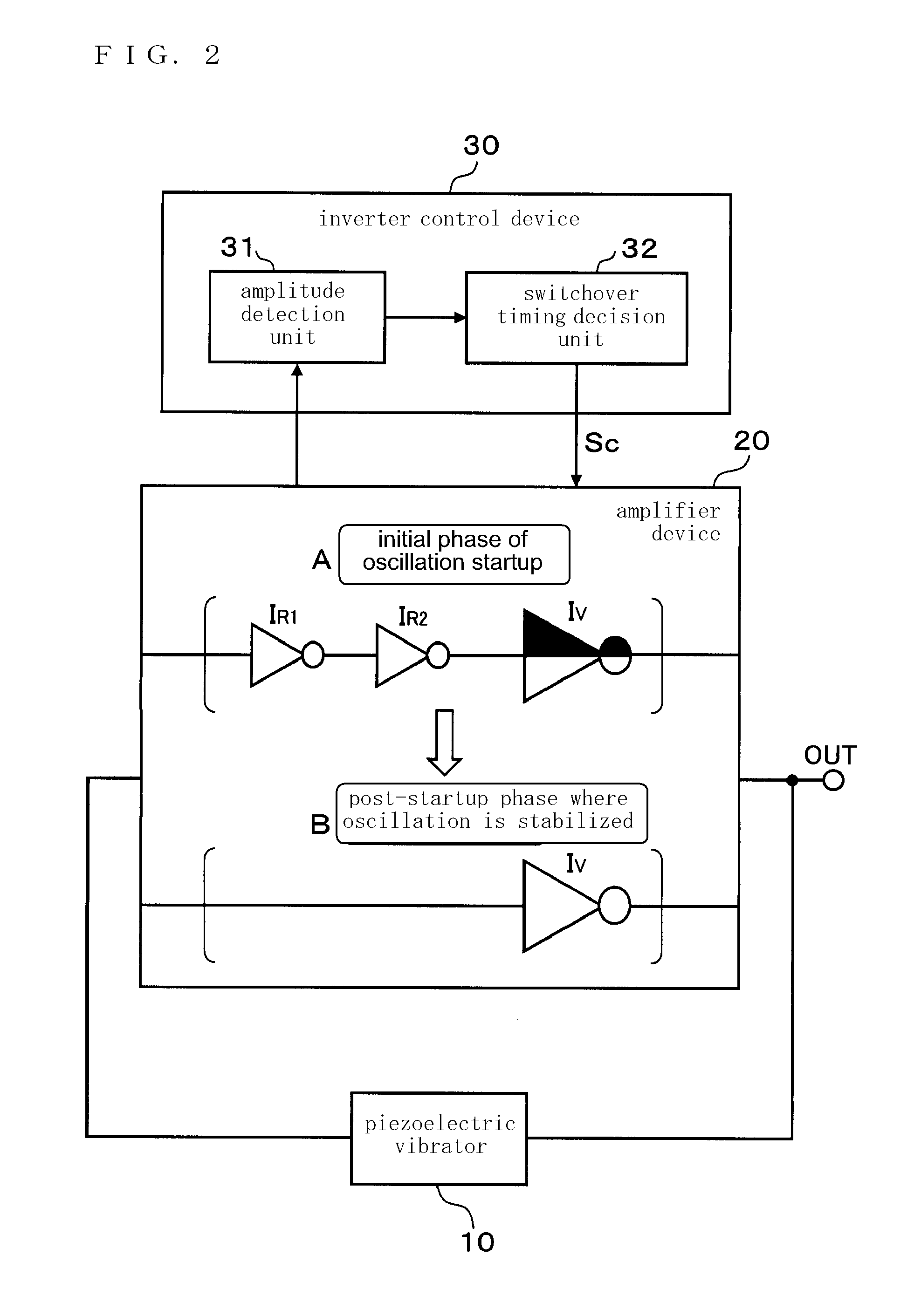
[0072]FIG. 4 is a circuit block diagram illustrating a structural characteristic of an oscillator circuit according to an exemplary embodiment 1 of the present invention. FIG. 5A illustrates a circuit configuration of main structural elements of the oscillator circuit in an initial phase of oscillation startup. FIG. 5B illustrates a circuit configuration of the main structural elements in a post-startup phase where the oscillation is stabilized. Referring to the drawings, 10 is a piezoelectric vibrator such as a quartz resonator, 20 is an amplifier device including inverters provided in a plurality of stages (IR1, IR2, IV) and configured to amplify an oscillation output of the piezoelectric vibrator 10, and 30 is an inverter control device which controls the inverters of the amplifier device 20. In the present exemplary embodiment, the inverter control device 30 includes an amplitude detection unit 31 and a switchover timing decision unit 32.

[0073]A first load capacitance C1 and a s...

exemplary embodiment 2

[0090]FIG. 9 is a circuit block diagram illustrating a structural characteristic of an oscillator circuit according to an exemplary embodiment 2 of the present invention. The oscillator circuit according to the present exemplary embodiment is a modified embodiment of the oscillator according to the exemplary embodiment 1, focusing on in which section of the amplifier device 20 the signal amplitude is detected by the amplitude detection unit 31 of the inverter control device 30. According to the exemplary embodiment 2, an input terminal of the amplitude detection unit 31 is connected to an output terminal of the amplifier device 20, and the amplitude detection unit 31 is configured to detect the amplitude of an output signal of the amplifier device 20 (see *1). Any other structural elements similar to those of FIG. 4 according to the exemplary embodiment 1 are simply illustrated with the same reference symbols, and description of the similar structural elements is omitted.

[0091]In th...

exemplary embodiment 3

[0095]FIG. 10 is a circuit block diagram illustrating a structural characteristic of an oscillator circuit according to an exemplary embodiment 3 of the present invention. The oscillator circuit according to the present exemplary embodiment is another modified embodiment of the oscillator according to the exemplary embodiment 1, focusing on in which section of the amplifier device 20 the signal amplitude is detected by the amplitude detection unit 31 of the inverter control device 30.

[0096]According to the exemplary embodiment 3, an input terminal of the amplitude detection unit 31 is connected to an input terminal of the amplifier device 20, and the amplitude detection unit 31 is configured to detect the amplitude of an input signal of the amplifier device 20 (see *2). Any other structural elements similar to those of FIG. 4 according to the exemplary embodiment 1 are simply illustrated with the same reference symbols, and description of the similar structural elements is omitted.

[...


PUM


Abstract

An oscillator circuit comprises a piezoelectric vibrator, an amplifier device including inverters provided in a plurality of stages, and an inverter control device. The inverters provided in the plurality of stages includes a performance-variable inverter configured which is operational in both of an initial phase of oscillation startup and a post-startup phase where the oscillation is stabilized and capable of a variable performance depending on whether the initial phase of oscillation startup or the post-startup phase where the oscillation is stabilized, and an ON/OFF inverter which is operational in the initial phase of oscillation startup and disconnected in the post-startup phase where the oscillation is stabilized. The inverter control device have the performance-variable inverter and the ON/OFF inverter both operational and lowers the performance of the performance-variable inverter in the initial phase of oscillation startup, and the inverter control device disconnects the ON/OFF inverter and increases the performance of the performance-variable inverter in the post-startup phase where the oscillation is stabilized.

Description

FIELD OF THE INVENTION[0001]The present invention relates to an oscillator circuit wherein an amplifier device which amplifies an oscillation output of a piezoelectric vibrator includes a plurality of inverter stages, and the number of operational inverter stages is increased in an initial phase of oscillation startup but decreased in a post-startup phase where the oscillation is stabilized, more particularly to a technology for reducing current consumption and preventing any abnormal oscillation resulting from over-performance while improving startup characteristics (quick startup of the oscillation) in the initial phase of oscillation startup, the technology further pursuing noise reduction and ensuring an operation stability in the post-startup phase where the oscillation is stabilized. The present invention is preferably applied to, for example, mobile telephone, automated meter reader, security and disaster control devices. The present invention is particularly serviceable for ...

Claims


Application Information

Patent Timeline
Patent Type & Authority Applications(United States)
IPC IPC(8): H03B5/32
CPCH03B2200/0046H03K3/0307H03B2200/0094H03B5/06H03B5/36H03L3/00
Inventor ISHIKAWA, SHINJIYAMANE, ICHIRO
Owner PANASONIC SEMICON SOLUTIONS CO LTD
Why Eureka
Try Eureka