Structured thermoplastic in composite interleaves

a technology of thermoplastic interleaf and composite interleaf, which is applied in the field of pre-pregs, can solve the problems of inability to cure thermoplastic interleaf layers, poor impact resistance, and inability to withstand high temperature, and achieves the effect of high strength

Active Publication Date: 2011-12-01
HEXCEL COMPOSITES LTD (GB)
View PDF6 Cites 44 Cited by
  • Summary
  • Abstract
  • Description
  • Claims
  • Application Information

AI Technical Summary

Benefits of technology

[0047]As an advantage of the present invention, the structured thermoplastic layers 14 and 16 or 24 may be made from different types of polyamides. This allows one to mix and match layers of polyamide, or other suitable thermoplastic polymer, within the interleaf zones of the laminate. Since the thermoplastic layers are structured, the placement of each particular type of polyamide can be carefully controlled. This type of directed polyamide placement is not possible with polyamide particles where a mixture of different particle types results in a homogenous blend within the interleaf zone.
[0048]As an example, thermoplastic polymer layer 14 would be a veil of PA6 / PA12 copolymer fibers and thermoplastic polymer layer 16 would be a veil of PA12 fibers. The resulting laminate 30 would include interleaf zones 32 in which discreet layers of PA6 / PA12 and PA12 are located. There are many other combinations possible depending upon the desired number of different thermoplastic polymers, the number of layers placed in each interleaf zone, the orientation and order of prepreg stacking to form the laminate and the orientation of the thermoplastic layers in the prepreg.
[0049]The structured thermoplastic polymer layers must be in a physical form that allows them to be substituted in place of particles in the interleaf zone. In particular, the layers must be sufficiently thin to fit within the interleaf zone and the density of the layer must be such that the appropriate amount or concentration of thermoplastic material is present in the interleaf zone to impart the desired amount of damage tolerance. Interleaf zones in cured high strength structural laminates typically have a thickness that ranges from 10 to 100 microns. Preferred interleaf zones range in mean thickness from 15 microns to 50 microns.
[0050]The structured thermoplastic layer should have a thickness that allows it to fit within the above interleaf zones along with a thermosetting resin. When more than one structured thermoplastic layer is to be located within an interleaf zone, as is the case with the laminate shown in FIG. 2, the combined thickness of the layers should be less than the desired interleaf zone thickness of the cured laminate. The thickness of the structured layer(s) should be no more than 95 percent of the desired interleaf zone thickness. Preferably, the thickness of the structured layer(s) will not be more than 75 percent of the desired interleaf zone thickness.
[0051]The thickness of the structured thermoplastic layers should be from 0.5 microns to 50 microns. The actual thickness for each layer will be determined by the intended thickness of the interleaf zone in the cured laminate, the number of layers desired in each interleaf zone, the density of the structured thermoplastic layer and the amount (concentration) of thermoplastic polymer that is desired within each interleaf zone. The preferred thickness range for the structured thermoplastic layers is front 2 microns to 35 microns and most preferably from 3 microns to 20 microns.
[0052]The density of the structured thermoplastic layer must be such that it provides the desired amount (concentration) of thermoplastic toughener to the interleaf zone. The needed density for the layer is directly dependent upon the thickness of the layer being used. The thinner the layer, the denser the layer must be in order to provide the same concentration of thermoplastic toughener in the interleaf zone. The density of the structured thermoplastic layer should be such that it provides a structured layer that has an areal weight of 1 to 20 grams per square meter (gsm) for layers that range from 0.5 to 50 microns in thickness. For preferred thermoplastic layers that are 2 to 35 microns thick, it is preferred that the density of the thermoplastic layer be such that the areal weight of the layer is from 2 gsm to 10 gsm. For layers that are from 3 to 20 microns thick, the density of the layer should be such that the areal weight of the layer is from 2 gsm to 8 gsm.

Problems solved by technology

However, although such cured materials have a number of clear benefits, it has long been known that they can suffer from poor impact resistance and be prone to delamination.
This is particularly the case when epoxy resin systems are used, which are known to tend to produce cured systems with low toughness.
Laminates that have interleaf layers toughened with thermoplastic particles have typically not been cured outside of an autoclave because curing at atmospheric pressure or below tends to produce cured laminates that have unacceptable mechanical properties for many structural applications including aerospace structural applications.
A lightning strike can cause damage to the composite material which can be quite extensive, and could be catastrophic if occurring on an aircraft structure in flight.
This is therefore a particular problem for aerospace structures made from such composite materials.

Method used


Image

  • Structured thermoplastic in composite interleaves
  • Structured thermoplastic in composite interleaves
  • Structured thermoplastic in composite interleaves

Examples


example 3

Prepreg C

[0132]A prepreg was manufactured by applying 36 gsm M56 resin films to either side of 134 gsm AS7-12K UD fibre and passing through consolidation rollers. Subsequently, 128D04 veil was then applied to one side of the prepreg before passing through a further set of consolidation rollers. The resultant prepreg according to the invention had a resin content of 35%.

example 1

Conductive Example 1

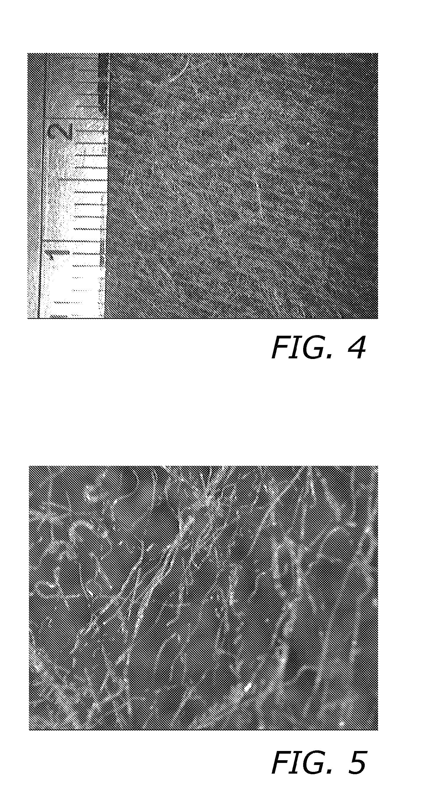
[0148]Eight plies of a M21E prepreg (available from Hexcel) were laid up (0 / 90). Between each ply was placed polyamide veil (PA 6) that had been coated with silver and then calendered (compressed) to produce a material that was both lightweight and very thin. The veil had a weight of 11 gsm and was 10-20 microns thick. Photomicrographs of the veil are shown in FIGS. 8 and 9 where the fibers are shown in white. The fibers have an average diameter of about 15 microns and a melting point of 252-260° C.

[0149]The prepreg was cured in an autoclave at 180° C. and 3 bar pressure. The through thickness resistance was determined as outlined above and the result shown in the Table 1 below and compared to a Comparative Example made by the same process and having interleaf layers comprising resin but without a sifter-coated veil.

TABLE 1Conductive ExamplesPanel descriptionThrough thickness resistance (Ohms)Comparative7.0ExampleExample 10.40

[0150]Images of cross-sections throug...

example 2

Conductive Example 2

[0151]8 plies of a M21E prepreg (available from Hexcel) were laid up to form a laminate of Sample A. This material was cured in an autoclave at 180° C. and 3 bar pressure. The through thickness resistance was determined as outlined above. 8 plies of a M21E prepreg containing 0.5 wt % of solid carbon microspheres in the resin were laid up to form a laminate of Sample B. This material was also cured in an autoclave at 180° C. and 3 bar pressure. The through thickness resistance was again determined. Finally, 8 plies of M21E prepreg with silver coated polyamide PA12 polymeric sheets in the interleafs between the plies were laid up to form a laminate of Sample C. Again the through thickness resistance was determined. The results are presented in the below Table 2.

TABLE 2Conductive ExamplesPanel descriptionThrough thickness resistance (Ohms)Sample A5-10Sample B0.4Sample C0.4

[0152]It should be noted that any of the veils described in Examples 1 and 3 can also be coated...


PUM

PropertyMeasurementUnit
thicknessaaaaaaaaaa
thicknessaaaaaaaaaa
pressureaaaaaaaaaa

Abstract

One or more layers of structured thermoplastic polymer, such as a light weight veil of thermoplastic polymer fibers, are located within the interleaf zone of laminates that are composed of fibrous layers and thermosetting resin. The thermoplastic veils are used in the interleaf zones as a replacement for thermoplastic toughening particles. The structured thermoplastic polymer may be coated with a conductive material to improve electrical conductivity through the laminate.

Description

[0001]This application is a continuation-in-part of copending PCT application No. PCT / IB2011 / 000728, which was filed on Apr. 4, 2011.BACKGROUND OF THE INVENTION[0002]1. Field of the Invention[0003]The present invention relates to prepregs comprising fibres and thermosetting resin which are stacked to form a laminate and subsequently cured to form a composite material. More particularly, the present invention involves the use of thermoplastic veil or other light weight structured thermoplastic material in the laminate interleaves. The present invention also relates to improvements in the electromagnetic response of composite materials, particularly to providing improved resistance to damage caused by lightning strikes.[0004]2. Description of Related Art[0005]Composite materials have well-documented advantages over traditional construction materials, particularly in providing excellent mechanical properties at very low material densities. As a result, the use of such materials is beco...

Claims


Application Information

Patent Timeline
Patent Type & Authority Applications(United States)
IPC IPC(8): B32B5/26C09J7/00C09J5/06
CPCB32B5/022B32B5/26B32B2255/02B32B2255/205Y10T428/269B32B2260/046B32B2262/0261B32B2605/18B32B2260/023Y10T428/31504Y10T442/654
Inventor SIMMONS, MARTINBLAIR, DANAMORTIMER, STEVE
Owner HEXCEL COMPOSITES LTD (GB)
Why Eureka
Try Eureka