Method for monitoring an scr catalytic converter

Inactive Publication Date: 2011-12-08
ROBERT BOSCH GMBH
View PDF1 Cites 33 Cited by
  • Summary
  • Abstract
  • Description
  • Claims
  • Application Information

AI Technical Summary

Benefits of technology

[0010]The method according to the invention is based on the concept of detecting NH3 slippage as soon as it starts to occur by means of a continuous observation and evaluation of the measured NOx conversion during the overdosing phase. It is therefore possible even at very low NH3 concentrations downstream of the SCR catalytic converter for a corresponding status message to be output in a targeted manner. According to the invention, therefore, to detect NH3 slippage, which indicates the transition from the overdosing phase to the underdosing phase, a variable which is characteristic of the NOx conversion is continuously measured during the overdosing phase, and in the event of a fall in the NOx conversion, it is inferred that NH3 slippage is present. This permits a very rapid and ear

Problems solved by technology

If the NH3 storage capacity is reduced on account of aging of or damage to the catalytic converter, an increased breakthrough or slippage of NH3 may occur, and the conversion of the nitrogen oxides no longer takes place to an adequate extent.
A problem with defining thresholds is however that, in the case of a threshold with only a small deviation from the normal state, the slippage detection is highly sensitive and there is the risk that even normal fluctuations in the NOx sensor signal downstream of the SCR catalytic converter lead to false detection of NH3 slippage.
This would lead to an underestimation of the NH3 storage capacity, and therefore to a false evaluation of the catalytic converter.
On the other hand, taking into consideration only large deviations from the normal state increases the reliability of the slippage

Method used


Image

  • Method for monitoring an scr catalytic converter
  • Method for monitoring an scr catalytic converter
  • Method for monitoring an scr catalytic converter

Examples


Embodiment Construction

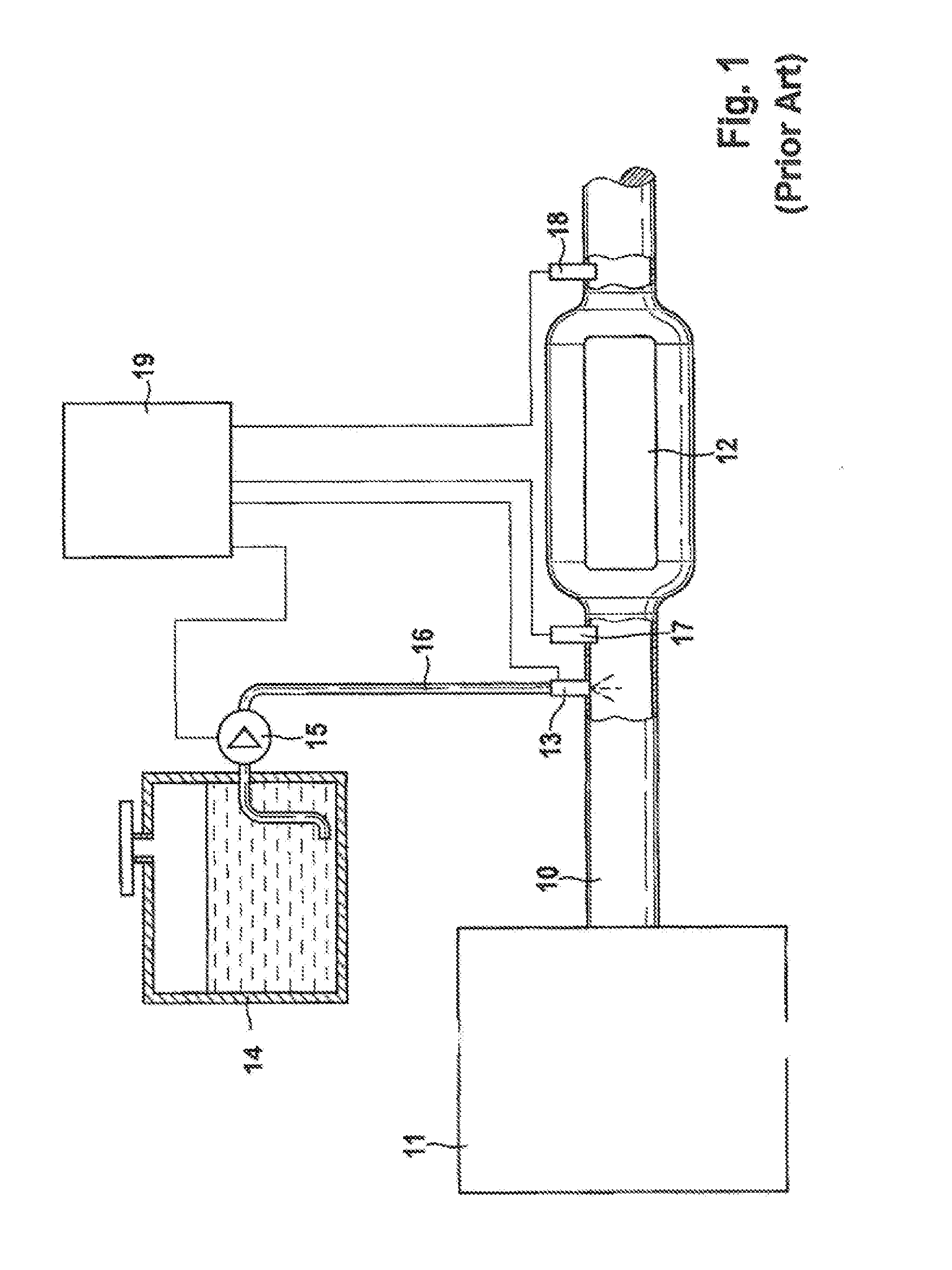
[0032]FIG. 1 firstly schematically shows the components, which are known per se, of a catalytic converter system. Arranged in the exhaust section 10 of an internal combustion engine 11 is an SCR catalytic converter 12 which selectively reduces nitrogen oxides in the exhaust gas by means of a selective catalytic reduction (SCR). For said reaction, ammonia (NH3) is used as reactant. Since ammonia is a toxic substance, said substance is gained from the non-poisonous carrier substance urea. The urea, in the form of liquid urea solution, is injected by means of the dosing device 13 into the exhaust section 10 upstream of the SCR catalytic converter 12. The aqueous urea solution is stored in a reducing agent tank 14 from which the solution is supplied to the dosing device 13 by means of a delivery pump 15 via a pressure line 16. To monitor the nitrogen oxide concentrations, a nitrogen oxide sensor 17 is provided upstream of the SCR catalytic converter 12 and a nitrogen oxide sensor 18 is ...


PUM


Abstract

A method is provided for monitoring an SCR catalytic converter (12), in which method the NH3 storage capacity of the SCR catalytic converter (12) is monitored. The SCR catalytic converter (12) is initially filled in an overdosing phase with a superstoichiometric reducing agent dosing up to the maximum NH3 storage capacity. The catalytic converter is subsequently acted on in an underdosing phase with a reducing agent dosing which is reduced in relation to a normal dosing or is absent. The NH3 storage capacity is indirectly determined during the underdosing phase by determining at least one characteristic value which is dependent on the NOx conversion rate. According to the invention, to detect NH3 slippage (25), which indicates the transition from the overdosing phase to the underdosing phase, a variable which is characteristic of the NOx conversion is continuously measured during the overdosing phase, and in the event of a fall in the NOx conversion, it is inferred that NH3 slippage (25) is present.

Description

BACKGROUND OF THE INVENTION[0001]The invention relates to a method for monitoring an SCR catalytic converter, in which an NH3 storage capacity of the SCR catalytic converter is monitored.[0002]Methods and devices for operating an internal combustion engine, in particular in a motor vehicle, in the exhaust-gas region of which is arranged an SCR catalytic converter (Selective Catalytic Reduction) by means of which the nitrogen oxides (NOx) contained in the exhaust gas of the internal combustion engine are reduced in the presence of a reducing agent to form nitrogen, are known. The proportion of nitrogen oxides in the exhaust gas can be considerably reduced in this way. For the reaction to take place, ammonia (NH3) is required, which ammonia is admixed to the exhaust gas. As reactant or reducing agent, therefore, use is made of NH3 or reagents which split off NH3. In general, use is made of an aqueous urea solution which is injected into the exhaust section upstream of the SCR catalyti...

Claims


Application Information

Patent Timeline
IPC IPC(8): G01M15/10
CPCF01N3/208F01N11/00F01N2550/02Y02T10/24F01N2900/1616F01N2900/1622Y02T10/47F01N2560/026Y02T10/12Y02T10/40
Inventor BASTOREALA, ARTHURFRANZ, ALEXANDERPFISTER, TOBIAS
Owner ROBERT BOSCH GMBH
Why Eureka
Try Eureka