Ionization chamber with temperature-controlled gas feed

a technology of ionization chamber and gas feed, which is applied in the direction of glass making apparatus, manufacturing tools, particle separator tube details, etc., can solve the problems of consuming side walls, requiring an enormous amount of work, and limiting the accuracy with which the corners and edges of the structure to be produced can be fabricated, so as to facilitate the monitoring of the temperature-control process, maximize the length of the gas channel, and reduce the effect of temperature changes

Active Publication Date: 2017-11-21
BRUKER DALTONIK GMBH & CO KG
View PDF22 Cites 0 Cited by
  • Summary
  • Abstract
  • Description
  • Claims
  • Application Information

AI Technical Summary

Benefits of technology

[0011]The sol-gel process is a method of producing non-metal inorganic or hybrid-polymeric materials from colloidal dispersions, so-called sols (derived from solution). From the starting materials or precursors in solution, a first step involves producing a gelatinous two-phase system containing both a liquid as well as a solid phase, whose consistency ranges from very fine particles to continuous polymer networks. By removing the residual liquid in a second step, for example in a drying process, the gel can be formed into solid bodies with a large variety of geometries, whose complexity is ultimately limited only by the form of the templates or casting molds. The sol-gel process is comparatively low-cost and, importantly, allows low-temperature processing of materials with high melting points, which can otherwise only be formed if a large amount of heat is applied. The method is particularly suitable for workpieces made of ceramic or glass materials, which have a lower risk of contamination than metals, for example.
[0016]The temperature-control block is preferably positioned on the ionization chamber in such a way that it forms part of an external boundary of the ionization chamber, or in other words is embedded into the wall of the ionization chamber in such a way that it forms part of the wall of the chamber. The consequent direct contact with the inside of the ionization chamber has the advantage that the gas is brought to the desired temperature in the immediate vicinity of the chamber, so temperature changes between the temperature-control device and the chamber remain small. This facilitates monitoring of the temperature-control process. Furthermore, the heat (or cold) accumulated in the material of the temperature-control block can additionally be used for the ionization chamber. If the temperature-control device is a heating device, for example, part of the wall of the ionization chamber is thus heated automatically, which counteracts the formation of undesired deposits at these points.
[0017]The temperature-control device at the gas channel serves to introduce heat into the gas channel or draw it away from it, i.e. to heat or cool the gas in the channel (temperature control), as required for the application in question. One example of a heating device would be a metal layer, or a layer of another electrical conductor, which is vapor deposited, sputter-deposited, or applied by means of a plasma beam onto one face of the formed part and equipped with electrical contacts so that an electric current passed through it produces resistive heat, which is released to the surroundings (for example the interior of the gas channel). In such a design it is expedient to maximize the length of the gas channel in the temperature-control block so that the gas flowing through is subjected to the heat input for as long as possible. The gas channel can meander through the temperature-control block or follow a labyrinth-like path, preferably utilizing the full dimensions of the block. In order to increase the efficiency of the heat transfer and to save material, it may be expedient for the applied conducting layer (or the temperature-control device in general) to largely follow the path of the gas channel in the formed part. In other words, the heat is only generated or emitted where it can be transferred to the gas in the channel. The energy used for the heating can thus be kept low and, at the same time, the thermal stress of the block material can be controlled and spatially limited also.

Problems solved by technology

This would require an enormous amount of work though, and the high costs involved practically exclude this type of production for commercial manufacture.
However, an etching method has the disadvantage that there is a limit to the accuracy with which corners and edges of the structure to be produced can be fabricated, and that the finished formed part must be cleaned to remove residual acid (very hazardous hydrofluoric acid, for example) which is a lengthy job.
Difficulties arise, furthermore, when the structures to be etched penetrate deep into the substrate, because the etching effect of the acid cannot be limited to the vertical direction, at least not without complicated precautions, but also eats into the side walls.
Moreover, what the two above-mentioned alternatives for fabricating formed parts have in common is that they are generally methods which remove material and thus increase material consumption.

Method used


Image

  • Ionization chamber with temperature-controlled gas feed
  • Ionization chamber with temperature-controlled gas feed
  • Ionization chamber with temperature-controlled gas feed

Examples


Embodiment Construction

[0031]While the invention has been shown and described with reference to a number of embodiments thereof, it will be recognized by those skilled in the art that various changes in form and detail may be made herein without departing from the scope of the invention as defined by the appended claims.

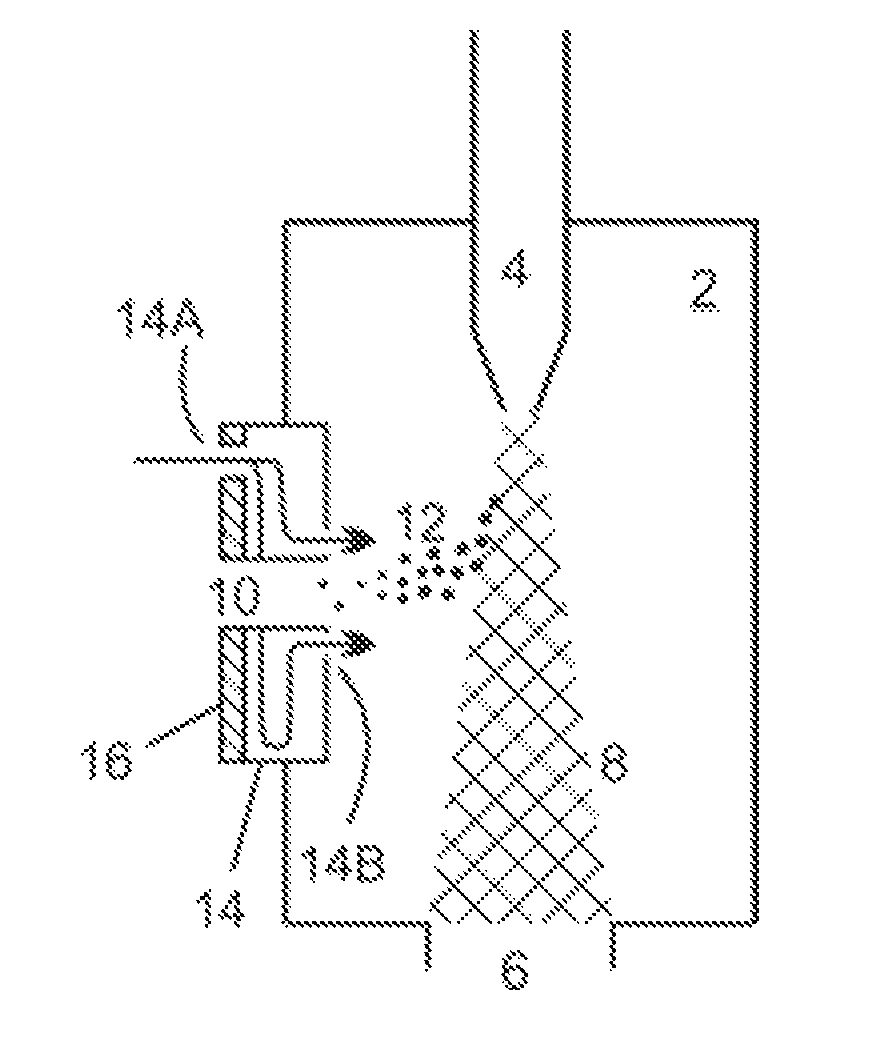
[0032]As has already been mentioned above, the invention proposes an ionization chamber with a temperature-controlled gas feed which is to be connected to a mass spectrometer, said ionization chamber having an advantageously formed temperature-control block for heating or cooling a gas which is to be fed into the chamber. Below, specific example embodiments of ionization chambers with temperature-control blocks are presented in a very schematic way and more to illustrate the general principles, from which the specialist can easily draw conclusions about the scope and the benefit of the new features according to the invention.

[0033]FIG. 1 shows a schematic cross-sectional, lateral view of a...


PUM

PropertyMeasurementUnit
pressureaaaaaaaaaa
pressureaaaaaaaaaa
pressureaaaaaaaaaa

Abstract

The invention relates to an ionization chamber for connection to a mass spectrometer. The ionization chamber has a temperature-control block with a gas inlet and a gas channel which starts at the gas inlet and leads into a gas outlet. A temperature-control device is positioned along the gas channel and ensures that a gas flowing in the gas channel is brought to a specific temperature, i.e. it is heated or cooled, before it enters the ionization chamber. The temperature-control block has a formed part into which a structure of the gas channel is incorporated and which is fabricated by means of a sol-gel process, for example out of a glass or ceramic material.

Description

BACKGROUND OF THE INVENTION[0001]Field of the Invention[0002]The invention relates to an ionization chamber to be connected to a mass spectrometer.[0003]Description of the Related Art[0004]In mass spectrometry, ionization chambers serve to provide gaseous phase ions from analytical samples, said ions being separated in a low-pressure region of a suitable mass analyzer according to their mass-to-charge ratio m / z and registered by a suitable detector. The chambers are usually isolated from their surroundings by means of a gas-tight enclosure in order to prevent the ambient atmosphere from interfering with the sample, and they usually contain only a few, well-defined fluid inflow and fluid outflow openings, such as a sample injector, an exhaust gas outlet or an ion transfer aperture to the vacuum stage of the mass analyzer.[0005]The prior art provides different types of ionization methods, of which only a few are mentioned here by way of example: electrospray (ESI), thermospray, matrix...

Claims


Application Information

Patent Timeline
Patent Type & Authority Patents(United States)
IPC IPC(8): H01J49/00H01J49/10H01J49/04
CPCH01J49/0486H01J49/10H01J49/0422H01J49/045H01J49/044H01J49/0477C04B35/14C03B19/12Y02P40/57H01J49/0468H01J49/049
Inventor BREKENFELD, ANDREASENGEL, MARTIN
Owner BRUKER DALTONIK GMBH & CO KG
Why Eureka
Try Eureka