Light guide film

a technology of light guide and film, which is applied in the field of light guide, can solve the problems of high failure rate, difficult manufacturing of v-cut light guide plate, and waste of electrical power consumption, and achieve the effects of high yield rate, easy manufacturing, and significant reduction of the thickness of the light guid

Active Publication Date: 2011-12-08
UBRIGHT OPTRONICS CORP
View PDF8 Cites 17 Cited by
  • Summary
  • Abstract
  • Description
  • Claims
  • Application Information

AI Technical Summary

Benefits of technology

[0012]The present invention provides a thin light guide film having a structure that is relatively easy to manufacture with high yield rate. In one aspect of the present invention, the light guide film is flexible. More particularly, the present invention provides a flexible light guide film having a light-adjusting structure in the form of a lenticular-like microstructure on the bottom side of the light guide film (i.e., the side facing away from the liquid crystal panel).
[0013]In one embodiment, the light guide film comprises a substrate layer supporting a layer light-adjusting structure. In a further embodiment, the light-adjusting structure comprises an array of longitudinal lenticular lenses laterally arranged in parallel. The light guide film may further comprise a prismatic-like microstructure on t

Problems solved by technology

Accordingly, a great deal of energy is required by the point or linear light source to produce planar light output of acceptable brightness, resulting in waste of electrical power consumption.
However, when it comes to V-cut light guide plate, a high failure rate is present as a result of difficulties associated with making the mold cavity and the nature of the above-described injection molding process.
The replica of the mold master having V-cut structures made by CNC precision-machining are often mal-manufactured and/or result in defects.
Therefore, the man

Method used


Image

  • Light guide film
  • Light guide film
  • Light guide film

Examples


Embodiment Construction

[0022]The present description is of the best presently contemplated mode of carrying out the invention. This invention has been described herein in reference to various embodiments and drawings. This description is made for the purpose of illustrating the general principles of the invention and should not be taken in a limiting sense. It will be appreciated by those skilled in the art that variations and improvements may be accomplished in view of these teachings without deviating from the scope and spirit of the invention. The scope of the invention is best determined by reference to the appended claims.

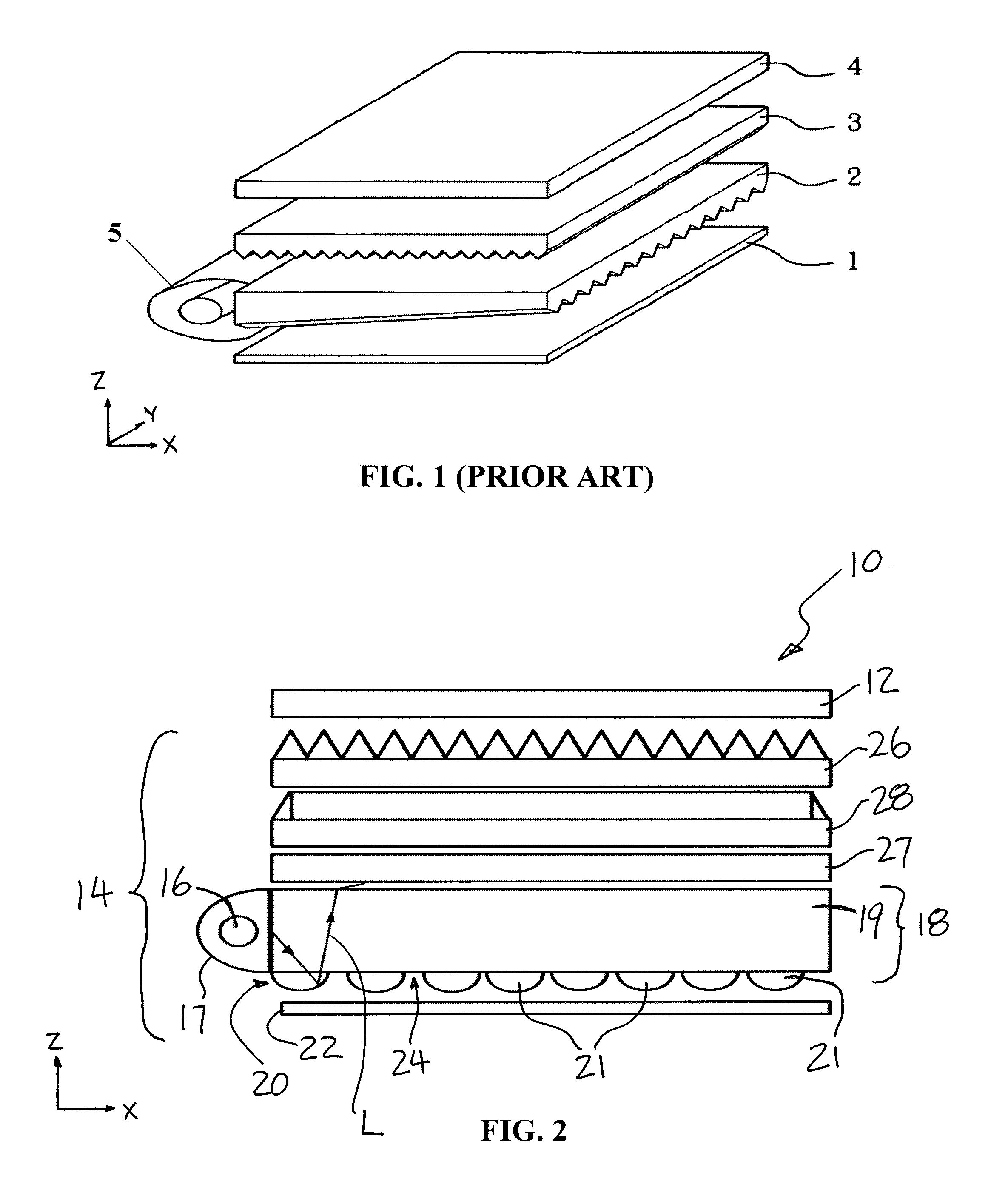
[0023]FIG. 2 schematically illustrates the structure of a backlight LCD device, which incorporates the light guide plate in accordance with one embodiment of the present invention. The backlight LCD 10, in accordance with one embodiment of the present invention, comprises a liquid crystal (LC) display module 12, a planar light source in the form of a backlight module 14, and a numbe...


PUM

PropertyMeasurementUnit
Volumeaaaaaaaaaa
Fractionaaaaaaaaaa
Lengthaaaaaaaaaa

Abstract

A flexible light guide film having a light-adjusting structure in the form of a lenticular-like microstructure on the bottom side of the light guide film. The light guide film has a substrate layer supporting a layer light-adjusting structure, which is in the form of an array of longitudinal lenticular lenses laterally arranged in parallel. A prismatic-like microstructure may be provided on the top light emitting side of the light guide film. The light guide film is fabricated by a process involving coating/embossing of a roll of sheet material, in a roll-to-roll continuous process. Advantages includes significantly reducing the thickness of the light guide film, and the roll-to-roll fabrication process provides for more precise replication of the microstructures on the master mold or drum onto the surface of the light guide film, which in turn reduces the failure rate and manufacturing cost.

Description

CROSS-REFERENCE TO RELATED APPLICATION[0001]The present application claims priority of U.S. Provisional Application Ser. No. 61 / 352,339 filed on Jun. 7, 2010. The present application is a continuation-in-part of U.S. patent application Ser. No. 13 / 073,859 filed on Mar. 28, 2011.[0002]All publications noted in the present application are incorporated by reference herein as if fully set forth herein.BACKGROUND OF THE INVENTION[0003]1. Field of Invention[0004]The present invention relates to light guides, particularly to light guides for use in flat panel displays, and more particularly to light guides for use in liquid crystal display panels.[0005]2. Description of Related Art[0006]In a liquid crystal display (LCD) panel, the liquid crystal (LC) layer does not emit light inherently, as compared to, for example, an electro-luminescent material layer in a plasma display panel. The LC layer or panel functions as a modulator of light transmitted through the LC layer. In a backlit LCD pane...

Claims


Application Information

Patent Timeline
IPC IPC(8): G02F1/13357G02B6/24
CPCF21S8/00Y10T156/1089G02B6/00G02B6/003G02F1/133615
Inventor WANG, KONG-HUAWANG, KAI-JINGYEH, FANG-CHUNYANG, CHING-ANHUANG, YI-CHUN
Owner UBRIGHT OPTRONICS CORP
Why Eureka
Try Eureka