Selective Catalytic Reduction Via Electrolysis of Urea
a catalytic reduction and electrolysis technology, applied in electrostatic separation, liquid-gas reaction process, machines/engines, etc., can solve the problems of reducing the heat transfer affecting the efficiency of the vaporization chamber, and requiring a substantial amount of heat and quickly stopping
- Summary
- Abstract
- Description
- Claims
- Application Information
AI Technical Summary
Benefits of technology
Problems solved by technology
Method used
Image
Examples
example 1
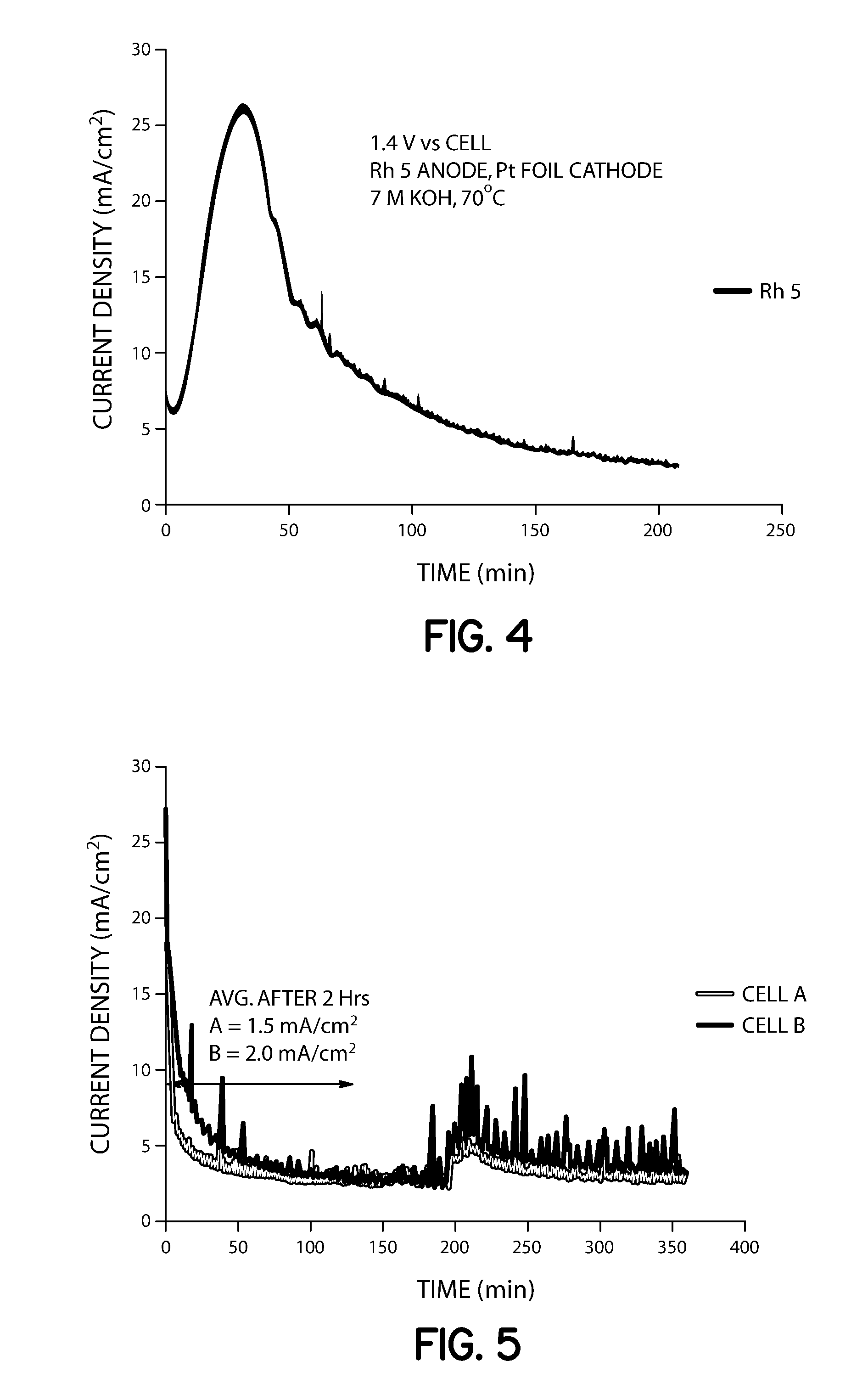
[0055]Two closed cells (1000 mL) were assembled. Each cell was filled with 200 mL of 7 M KOH and 0.33 M urea solution, and stirred at 120 rpm. Voltage (1.4 V) was applied to cell B (supplied with Arbin Industries MSTAT) using a Rh—Ni anode (0.15 mg / cm2 Rh on Ni foil, 10 cm2) and platinum foil (10 cm2) as the cathode. Samples were taken via liquid sampling ports and analyzed for ammonia concentration periodically by extracting 10 mL and diluting 1:100 with distilled water. A 50 mL aliquot of this analyte was added to a flask, 1 mL of pH adjusting solution was added with stirring, and the solution was analyzed using an ion selective electrode. After two hours of constant voltage operation, Cell A and B contained aqueous ammonia concentrations of 3600 and 4700 ppm, respectively (Table 1). After 3 hours of operation, cell A increased to 3800 ppm while cell B increased to 6450 ppm, which provided that the cell with applied potential had 41% higher conversion of urea to ammonia. Cell B av...
example 2
[0057]Two closed cells (1000 mL) were assembled with Rh—Ni anodes (8 cm2 each; cell A: 0.05 mg / cm2, cell B: 0.15 mg / cm2) and platinum foil cathodes (15 cm2), filled with 7 M KOH and 0.33 M urea, and heated to 70° C. Liquid sampling ports were included for monitoring aqueous ammonia concentration ex-situ by ISE throughout the duration of the experiment. Voltage (1.33 V) was applied to both cells A and B (supplied with Arbin Industries MSTAT) with 120 rpm stirring. A lower voltage was chosen as compared to Example 1 above because it was postulated that a lower voltage, which will provide a lower current density, was needed to affect the NiOOH catalyzed reaction to ammonia.
[0058]Samples were taken and analyzed for ammonia concentration periodically by extracting 10 mL and diluting 1:100 with distilled water. A 50 mL aliquot of this analyte was added to a flask with stirrer and ISE electrode and 1 mL of pH adjusting solution, as described in Experiment 1. After two hours of constant vol...
example 3
[0062]Electrolytic Hydrolysis of Urea: A cell containing 7 M KOH / 0.33 M urea solution at atmospheric pressure was subjected to electrolysis-induced hydrolysis. A cell voltage of 1.4 volts was applied to a 2×2.5 cm2 carbon-paper anode deposited with Ni, and a 5×5 cm2 Pt foil cathode. Under these conditions, the presence of ammonia was detected from the conversion of urea into ammonia and carbon dioxide. The hydrolysis pathway becomes favorable with increasing hydroxide salt concentration and increasing temperatures. For example, urea samples contained in 0 M, 1 M, 5 M and 7 M KOH at 50° C. for 89 hours produced 0.7%, 4.2%, 27.4 and 36.7% hydrolysis, respectively. A 7 M KOH sample of urea at 70° C. for 24 hours provided over 95% hydrolysis.
PUM
| Property | Measurement | Unit |
|---|---|---|
| Molar density | aaaaa | aaaaa |
| Volume | aaaaa | aaaaa |
| Volume | aaaaa | aaaaa |
Abstract
Description
Claims
Application Information
 - R&D
- Intellectual Property
- Life Sciences
- Materials
- Tech Scout
- Unparalleled Data Quality
- Higher Quality Content
- 60% Fewer Hallucinations
Browse by: Latest US Patents, China's latest patents, Technical Efficacy Thesaurus, Application Domain, Technology Topic, Popular Technical Reports.
© 2025 PatSnap. All rights reserved.Legal|Privacy policy|Modern Slavery Act Transparency Statement|Sitemap|About US| Contact US: help@patsnap.com


