
Method and apparatus for off-line testing of multi-phase aternating current machines

a multi-phase alternating current machine and test method technology, applied in the direction of dynamo-electric machine testing, resistance/reactance/impedence, instruments, etc., can solve the problems of inability to measure the electric motor, excessive resistance, excessive air cavity, etc., to reduce the time required for testing the machine, and fast and reliable determination

Active Publication Date: 2011-12-15
SUBSEE RAA
View PDF6 Cites 8 Cited by
  • Summary
  • Abstract
  • Description
  • Claims
  • Application Information

AI Technical Summary

Benefits of technology

[0009]A particular object is to provide a convenient, reliable and time efficient method for testing a multi-phase alternating current machine.
[0013]By summing physical stator quantities of each phase, a first joint physical stator quantity which is independent of the rotor position may be determined. Furthermore, no rotation of the rotor needs to be performed during the testing even though rotation of the rotor is allowed during testing. This simplifies the testing and reduces the time required for testing the machine and also eliminates any problems of asymmetry in measurement data due to non-continuous rotation of the rotor.
[0020]As discussed above, by summing physical stator quantities of each phase, a second joint physical stator quantity which is independent of the rotor position may be determined. Specifically, the rotor does not need to be rotated to the rotor position for which the first joint physical stator quantity was established. Furthermore, no rotation of the rotor needs to be performed during the testing even though rotation of the rotor is allowed during testing. This simplifies the testing and reduces the time required for testing the machine and also eliminates any problems of asymmetry in measurement data due to non-continuous rotation of the rotor.
[0027]According to one embodiment, the first joint physical stator quantity corresponds to a joint physical stator quantity established for the multi-phase alternating current machine in a functioning state. In this description, a machine in a functioning state refers to a machine which is known to be fault-free, i.e. free from defects. This knowledge may have been gained from earlier elaborate testing of the machine, optical inspection etc. for instance during production and assembly of the machine, i.e. at a time when thorough testing of the machine was feasible. This embodiment provides the advantage that the first joint physical stator quantity is known to be a reliable reference. As discussed earlier, for a machine in a functioning state the first joint physical stator quantity may be independent of the rotor position.
[0030]According to one embodiment, the first joint physical stator quantity is determined for a first rotor position, different from the second rotor position. Or to put it differently, the rotor does not need to be rotated to the rotor position for which the first joint physical stator quantity was established in order for the testing to work. This is due to the rotor position independence of the first and second joint physical stator quantities.

Problems solved by technology

Common types of rotor faults are, for example, breaks or cracks / fractures in a rotor bar, excessively high resistance in welded or soldered joints in the rotor, excessively large air cavities (as a result of the casting of the rotor) and rotor offset in air gaps relatively to the stator.
Common types of stator faults are, for example, insulation faults between the turns of a winding, insulation faults between windings in the same phase, insulation faults between windings in different phases, insulation faults between windings and earth / motor casing, contaminated windings (i.e. impurities such as moisture, dust, or insulation charred due to overheating), an open turn of a winding in a delta-connected motor as well as contact problems between the winding ends and external connections.
These disturbances cause erroneous measuring results and may even make measurements on the electric motor impossible.
This measuring method has many disadvantages, such as it may initiate or accelerate / bring to completion incipient insulation failures; it requires time-consuming and complex calculations and analysis; it causes problems of pulse propagation in the winding due to L and C effects; it requires bulky and heavy equipment associated with transport / installation problems; and it is an expensive method.
Normally, this asymmetry would indicate a rotor / stator fault, but could also be due to non-continuous rotation.
Since it may be difficult under some circumstances to obtain a perfect rotation of the rotor, either by continuous rotation or at fixed steps, especially when rotating the rotor by hand, this requirement may be hard to fulfill for the above described technique under these circumstances.
Under some circumstances it may even be difficult or impossible to rotate the rotor at all during off-line testing.

Method used


Image

  • Method and apparatus for off-line testing of multi-phase aternating current machines
  • Method and apparatus for off-line testing of multi-phase aternating current machines
  • Method and apparatus for off-line testing of multi-phase aternating current machines

Examples


Embodiment Construction

)

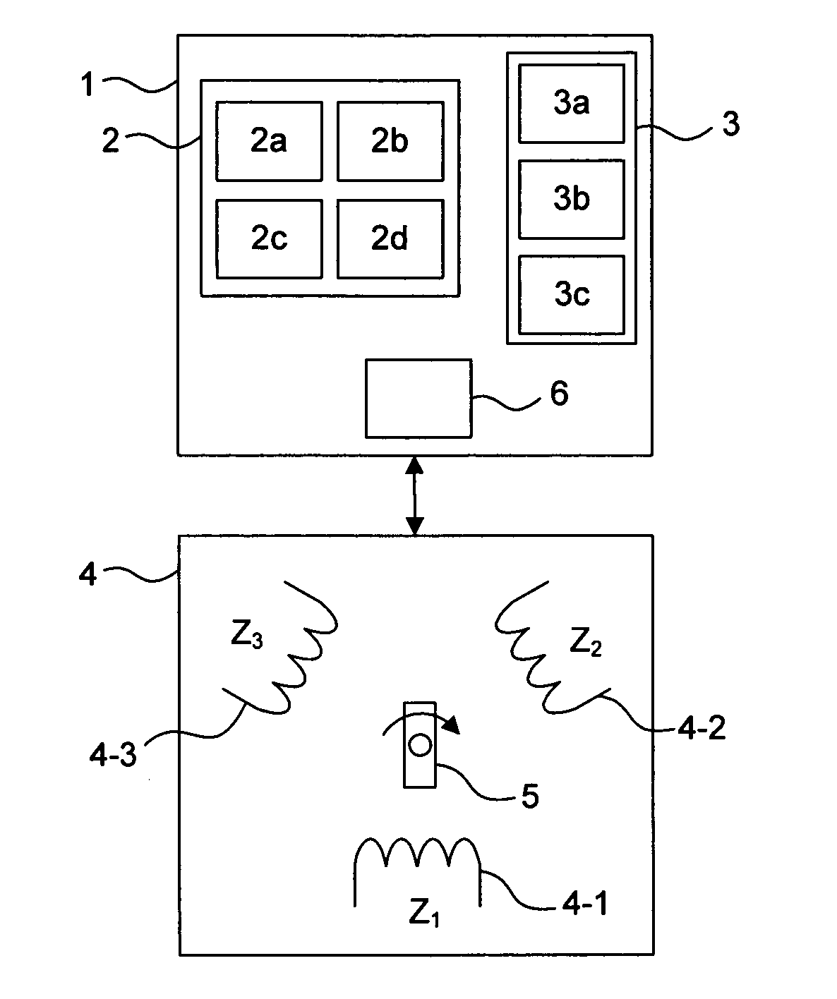
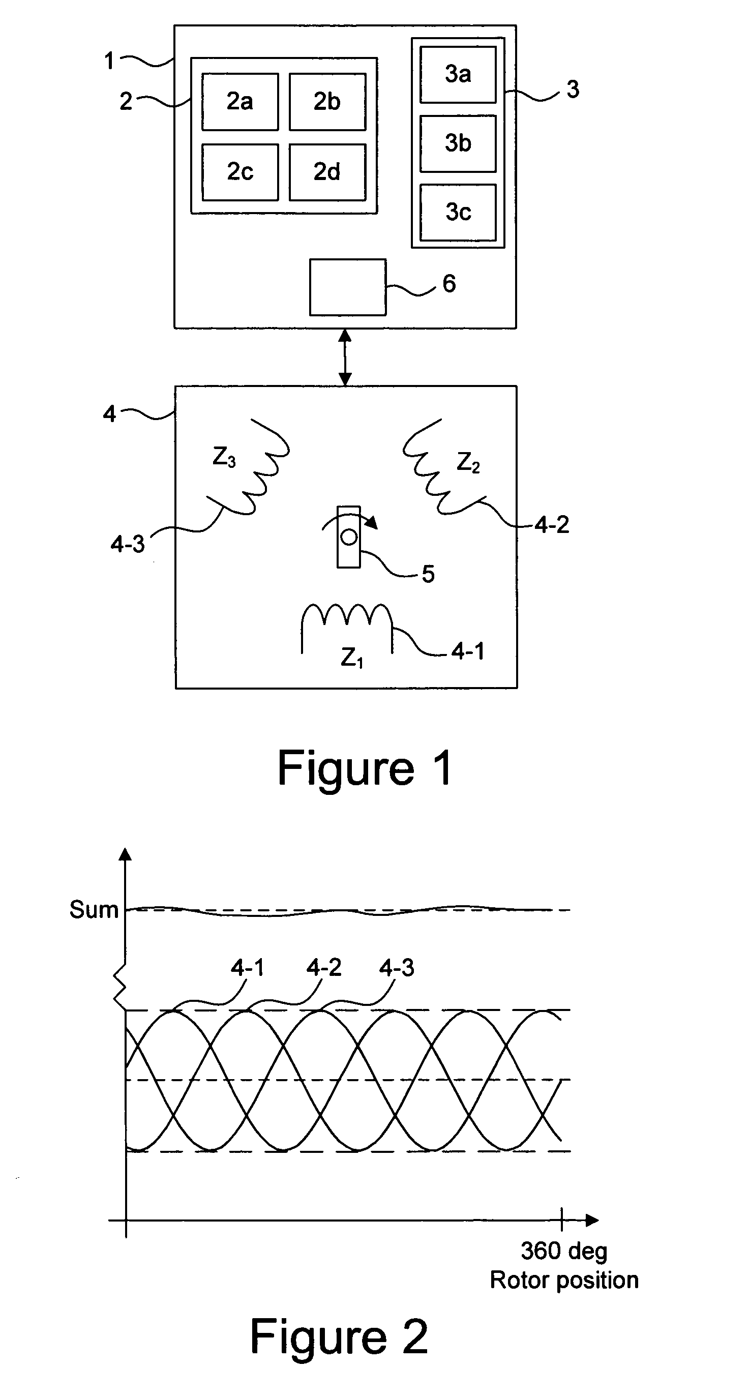
[0050]A system in which the present invention may be applied will first be described with reference to FIG. 1.

[0051]Referring to the block diagram in FIG. 1, a preferred embodiment of a measuring device 1 according to the present invention will be described. The measuring device 1 comprises a control unit 2, which preferably comprises: a CPU 2a, a program memory 2b, a data memory 2c, and an A / D converter 2d. The measuring device further comprises a measuring circuit 6. The measuring device 1 may additionally comprise a screen, which is connected to the control unit 2.

[0052]The measuring device 1 comprises a waveform generator 3 connected to the control unit 2, which preferably comprises: a D / A converter 3a, a reconstruction filter 3b and a power amplifier 3c.

[0053]The measuring device 1 comprises inputs for connection to a test object 4.

[0054]The test object 4 is a multi-phase alternating current machine. The machine may be a two-phase machine, a three-phase machine, a six-phase o...


PUM


Abstract

A method and apparatus are provided for off-line testing of a multi-phase alternating current machine. The method comprises determining, at a first rotor position, a physical stator quantity of each stator winding by applying a test signal to each stator winding, and determining a first joint physical stator quantity by summing the determined physical stator quantities of the stator windings. There is also provided a method and apparatus for off-line testing of a multi-phase alternating current machine. The method comprises determining, at a second rotor position, a physical stator quantity of each stator winding by applying a test signal to each stator winding, determining a second joint physical stator quantity by summing the determined physical stator quantities of the stator windings, comparing the second joint physical stator quantity with a previously determined first joint physical stator quantity, and determining a fault condition of said multi-phase alternating current machine if the first joint physical stator quantity differs from the second joint physical stator quantity

Description

FIELD OF THE INVENTION[0001]The present invention relates to testing of multi-phase alternating current machines. More specifically the present invention relates to a method and apparatus for off-line testing of multi-phase alternating current machines.BACKGROUND ART[0002]Electric motors have a wide field of application. In industrial production, for example, electric motors are used to drive pumps, conveyor belts, overhead cranes, fans, etc. An electric motor, adapted for use in a specific application, offers the user many advantages, mainly owing to its long life and limited need for maintenance. One basic requirement for a long electric motor life is that the rotor or stator in the electric motor does not have any faults or defects. Common types of rotor faults are, for example, breaks or cracks / fractures in a rotor bar, excessively high resistance in welded or soldered joints in the rotor, excessively large air cavities (as a result of the casting of the rotor) and rotor offset ...

Claims


Application Information

Patent Timeline
Patent Type & Authority Applications(United States)
IPC IPC(8): G01R31/34
CPCG01R31/34G01R27/02
Inventor COP, BORIS
Owner SUBSEE RAA
Learn More