Optical Multi-Level Transmission System

a transmission system and optical multi-level technology, applied in the field of optical information transmission technology, can solve the problems of significant degraded reception sensitivity, and achieve the effect of improving the efficiency of optical multi-level transmission

Inactive Publication Date: 2011-12-15
HITACHI LTD
View PDF5 Cites 41 Cited by
  • Summary
  • Abstract
  • Description
  • Claims
  • Application Information

AI Technical Summary

Benefits of technology

[0065]Further, when the polarization multiplexing is employed in this invention, there is obtai

Problems solved by technology

In the case where the anisotropic noise is generated, when the conventional isotropic signal constellation and isotropic decision method are used, a symbol decision

Method used


Image

  • Optical Multi-Level Transmission System
  • Optical Multi-Level Transmission System
  • Optical Multi-Level Transmission System

Examples


first embodiment

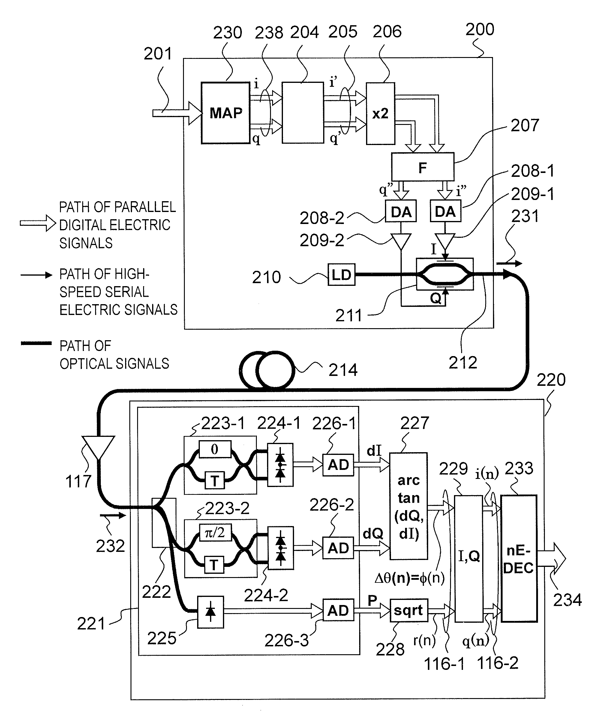
[0101]FIG. 5 is a block diagram illustrating a phase pre-integration incoherent optical multilevel transmission system according to this invention.

[0102]Hereinafter, a path of optical signals is indicated by a bold line, a path of electric signals is indicated by a thin line, and a path of parallel digital electric signals using a plurality of signal wires is indicated by white open arrows. This configuration is an incoherent optical multilevel transmission system using a phase pre-integration optical field transmitter 200 and an incoherent optical field receiver 220.

[0103]A first difference between the conventional technology illustrated in FIG. 4 and this embodiment resides in a symbol decision circuit inside the incoherent optical field receiver 220, and in this embodiment, a symbol decision circuit 233 which uses an amplitude-weighted non-Euclidean distance is used.

[0104]A second difference between the conventional technology illustrated in FIG. 4 and this embodiment resides in ...

second embodiment

[0132]FIG. 8 is an explanatory diagram illustrating a signal constellation of 8QAM modulation according to this invention, and a decision area for a received symbol based on the non-Euclidean distance.

[0133]This invention takes an example in which an 8QAM signal is used as the modulation signal and in which the non-Euclidean distance d(X,Y) is used to define the decision area. In this example, in dE(x,y)=|x-y|̂2+a(|x|−|y|) ̂2, the amplitude weight a is set to 2. As a result, the decision areas for all the symbols are enlarged to near 90 degrees in the angular direction on the dotted circumference on which each symbol is located, and hence the resistance to the noise in the angular direction is significantly improved compared to the decision areas described above with reference to FIG. 7B. Further, the boundary lines generally coincide with sparse regions of the eight distributions of black dots, which also demonstrates that near-ideal decision can be made.

third embodiment

[0134]FIGS. 9A to 9C are explanatory diagrams each illustrating a signal constellation and decision areas for the received symbol based on the non-Euclidean distance of 16QAM modulation according to this invention.

[0135]FIGS. 9A to 9C are explanatory diagrams illustrating the signal constellation and a decision area for a received symbol based on a non-Euclidean distance when the weight a is set to 1 to 3 of the 16QAM modulation according to the third embodiment of this invention.

[0136]This invention takes an example in which the 16QAM signal is used as the modulation signal and in which the non-Euclidean distance d(X,Y) is used to define the decision area. The definition of d(X,Y) in this example is the same as the second embodiment, but the amplitude weight a is changed to examine the change in the decision area. FIGS. 9A to 9C illustrate cases where a=1, a=2, and a=3, respectively, and it can be seen from the figures that as the amplitude weight a is set larger, the width of the ...


PUM


Abstract

Provided is an optical multilevel transmission system, comprising at least one optical multilevel transmitter for transmitting an optical multilevel signal obtained and an optical multilevel receiver for receiving the optical multilevel signal. The received optical multilevel signal has a larger noise in an angular direction than in a radial direction. The optical multilevel receiver sets, in a symbol decision of the received optical multilevel signal demodulated on the complex plane, for positions of all or some of ideal signal points, a width in the angular direction of a decision area, to which each of the ideal signal points belongs and which is measured along a circumference of a circle centered at an origin and passing through a center of the each of the ideal signal points, larger than a width in the angular direction of a decision area defined based on a Euclidean distance.

Description

BACKGROUND OF THE INVENTION[0001]This invention relates to an optical information transmission technology, and more particularly, to an optical field transmitter and an optical field transmission system suitable for transmission / reception of an optical multilevel signal transmitted via an optical fiber.[0002]The amount of information that can be transmitted (transmission capacity) via one optical fiber has reached its capacity limit because a wavelength bandwidth of an optical fiber amplifier has been almost used up owing to an increase in number of wavelength channels and a speedup of a modulation speed of an optical signal. In order to further expand the transmission capacity of the optical fiber, it is necessary to improve efficiency of the frequency bandwidth usage by devising a signal modulation method so that a large number of optical signals are packed in a limited frequency bandwidth.[0003]In the world of radio communications, since 1960s, a multilevel modulation technology ...

Claims


Application Information

Patent Timeline
IPC IPC(8): H04B10/00H04J14/02H04J14/06H04B10/12H04B10/50H04B10/54H04B10/67H04B10/69
CPCH04B10/5055H04B10/541H04L27/3845H04B10/695H04L25/061H04B10/676
Inventor KIKUCHI, NOBUHIKO
Owner HITACHI LTD
Why Eureka
Try Eureka