Component for a gas turbine and a method for the production of the component

a gas turbine and component technology, applied in the direction of turbines, machines/engines, manufacturing tools, etc., can solve the problems of reducing the reliability and service life of the joining zone, affecting the durability of the component joint, and reducing the lattice vacancy, so as to reduce the diffusion rate of atoms, increase the lattice tension in the matrix, and reduce the effect of lattice vacancy

Inactive Publication Date: 2011-12-15
MTU AERO ENGINES GMBH
View PDF43 Cites 31 Cited by
  • Summary
  • Abstract
  • Description
  • Claims
  • Application Information

AI Technical Summary

Benefits of technology

[0016]Incorporating the metal particles into the matrix alloy first increases the lattice tension in the matrix and reduces the lattice vacancies. This reduces the diffusion rate of the atoms that diffuse through the interlayer. Moreover, the metal particles distributed in the matrix alloy can pick up the aluminum and titanium molecules that are diffusing out of the titanium alloy of the second layer of the adapter element or of the rotor blade, either in dissolved form or bonded as intermetallic phases. Owing to the low mobility of the atoms of the refractory metals or of the platinum metals and owing to the formation of intermetallic phases, the metal particles are very stable at temperatures of up to 800° C. [1472° F.]. In this manner, the diffusion of the titanium and aluminum through the interlayer is greatly hindered at the working temperature, and the formation of intermetallic phases is reduced in t

Problems solved by technology

Up until now, it has not been possible to create a hybrid or graduated blisk design for a gas turbine rotor in which the rotor base is made of a high temperature-resistant nickel alloy such as, for instance, Inconel 718, while the turbine blades are made of a TiAl al

Method used


Image

  • Component for a gas turbine and a method for the production of the component
  • Component for a gas turbine and a method for the production of the component
  • Component for a gas turbine and a method for the production of the component

Examples


Embodiment Construction

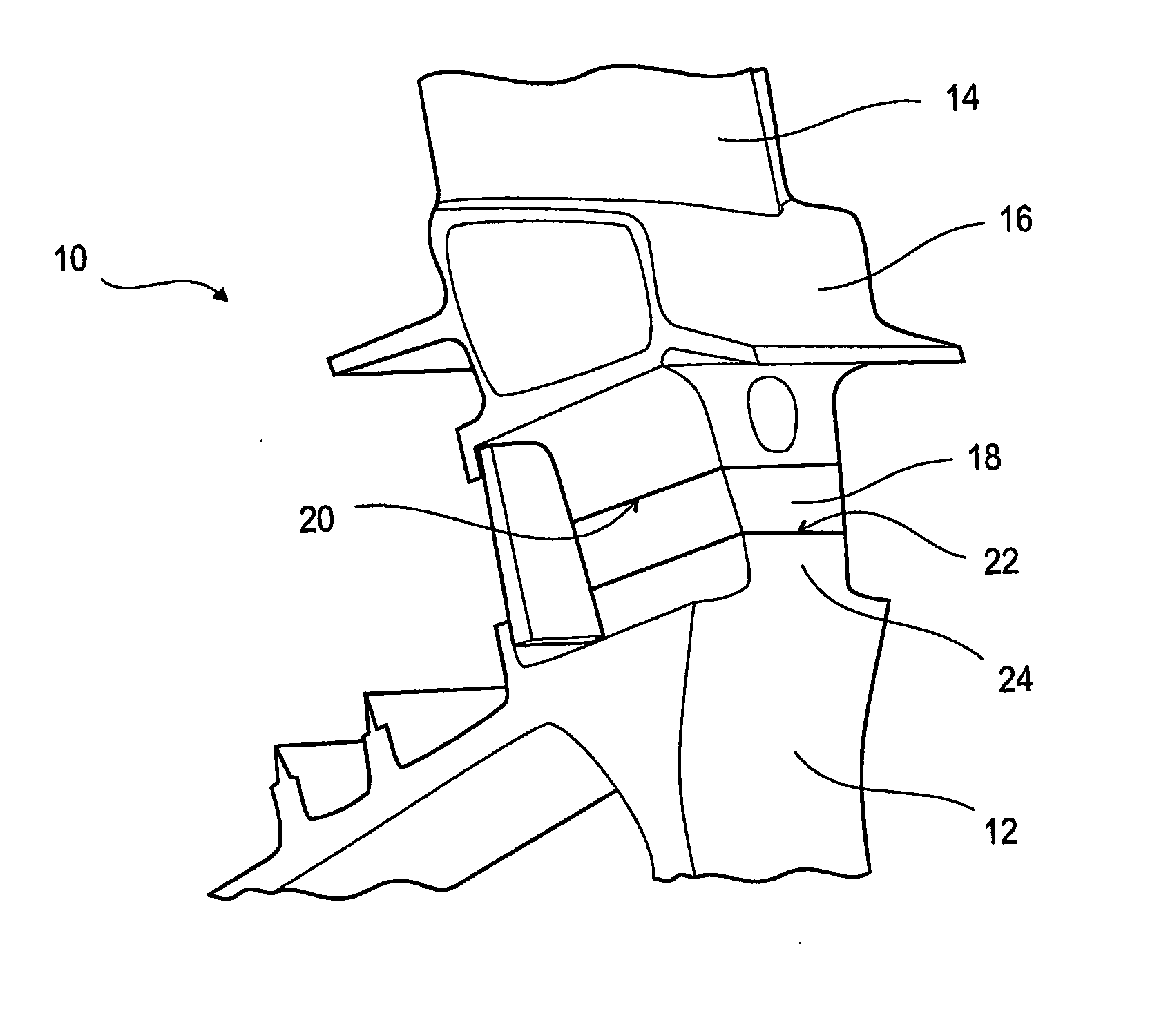
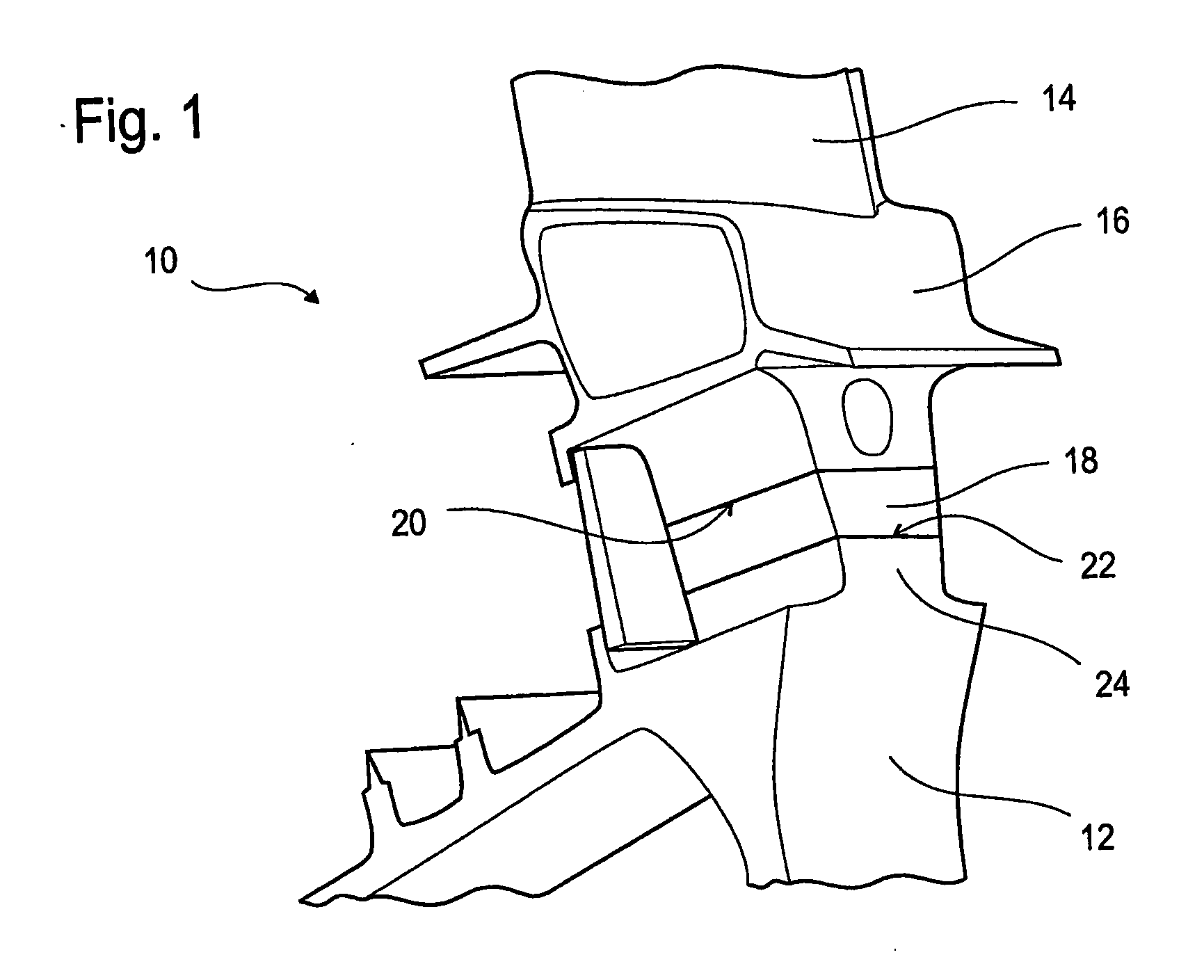
[0029]FIG. 1 shows a schematic view of a gas turbine rotor 10 preferably for a gas turbine of an aircraft engine, said turbine rotor being configured as a rotor with integrated blades. Accordingly, the gas turbine rotor 10 has a rotor base 12 as well as turbine blades 14, whereby the turbine blades 14 are an integral part of the rotor base 12.

[0030]Such a rotor with integrated blades is also referred to as a blisk (blade integrated disk) or as a bling (blade integrated ring), depending on whether the rotor base is disk-shaped or ring-shaped.

[0031]The rotor base 12 is made of a high temperature-resistant nickel alloy, preferably a nickel superalloy such as Inconel 718.

[0032]A plurality of turbine blades 14—only one of which is shown in FIG. 1—is joined to the rotor blade 12. The turbine blades 14 each comprise a rotor blade 16 made of a titanium alloy as well as a blade root that is configured as an adapter element 18.

[0033]The titanium alloy of the rotor blade 16 is preferably selec...


PUM

PropertyMeasurementUnit
Fractionaaaaaaaaaa
Fractionaaaaaaaaaa
Fractionaaaaaaaaaa

Abstract

A component for a gas turbine, especially a blisk or a bling, whereby the component includes a rotor base (12) made of a high temperature-resistant nickel alloy and a plurality of turbine blades (14) joined to the rotor base, whereby each turbine blade includes a rotor blade (16) made of a titanium alloy and a blade root. The blade root is configured as an adapter element (18) that is made of a material that can be welded to the titanium alloy as well as to the high temperature-resistant nickel alloy and that is integrally joined to the rotor base (12) and to the rotor blade (16) fusion. A method for the production of the component is also described.

Description

[0001]The invention relates to a component for a gas turbine as well as to a method for the production of the component.[0002]Gas turbine rotors have a rotor base as well as several turbine blades that rotate together with the rotor base. The turbine blades can either be an integral part of the rotor base or else they can be anchored by means of blade roots in one or more grooves in the rotor base. Rotors with integrated blades are referred to as blisks or blings, depending on whether the rotor base is disk-shaped or ring-shaped.BACKGROUND[0003]German patent application DE 10 2005 019 356 A1 discloses a method for joining a turbine blade to a rotor base during the production or repair of a gas turbine rotor with integrated blades by means of friction welding. In friction welding, components are fused together by friction and integrally joined to each other. In linear friction welding, one component is moved back and forth translatorily, while the other component is stationary and it...

Claims


Application Information

Patent Timeline
IPC IPC(8): F01D5/14B23P15/02
CPCB23K20/1205B23K2201/001B23K2203/14B23P15/006F01D5/34Y10T29/49968F05C2201/0466F05D2230/50F05D2300/133Y10T29/49336Y10T29/49337F05B2230/239B23K2101/001B23K2103/14F01D5/3061
Inventor SMARSLY, WILFRIEDESSLINGER, JOERG
Owner MTU AERO ENGINES GMBH
Why Eureka
Try Eureka