Heat exchanger for an annealing furnace for exchanging heat between two fluids

a technology of heat exchanger and annealing furnace, which is applied in the direction of muffle furnace, heat treatment apparatus, furnace, etc., can solve the problems of reducing the effectiveness of the plant, increasing the heating time of the heat exchanger, and preventing the application of particularly strong dynamic temperature fluctuations, etc., to achieve low material input, simple and cost-effective possibility, and low inherent heat storage capacity

Inactive Publication Date: 2011-12-22
EBNER-INDUSTRIEOFENBAU GMBH
View PDF8 Cites 2 Cited by
  • Summary
  • Abstract
  • Description
  • Claims
  • Application Information

AI Technical Summary

Benefits of technology

[0005]The invention provides an especially simple and cost-effective possibility for producing a heat exchanger which is suitable for an annealing furnace which as a result of its low inherent heat storage capacity can realize especially dynamic temperature fluctuations in the annealing furnace in combination with an especially low material input and thus low weight. Since the profile is a profile tube made of folded sheet, not only the outside jacket surface of the heat exchanger increases in the heat exchanger in accordance with the invention, as is the case in the state of the art, but also the inside jacket surface of the heat exchanger, thus better utilizing the energy contained in the hot gas on the one hand and enabling the realization of higher thermal energy flows with heat exchangers that are of the same size in respect of the state of the art o

Problems solved by technology

It is disadvantageous in the known heat exchangers however that they are made of massive heat-resistant material such as cast or ceramic materials, which not only increases the heating time of the heat exchanger as

Method used


Image

  • Heat exchanger for an annealing furnace for exchanging heat between two fluids
  • Heat exchanger for an annealing furnace for exchanging heat between two fluids
  • Heat exchanger for an annealing furnace for exchanging heat between two fluids

Examples


Embodiment Construction

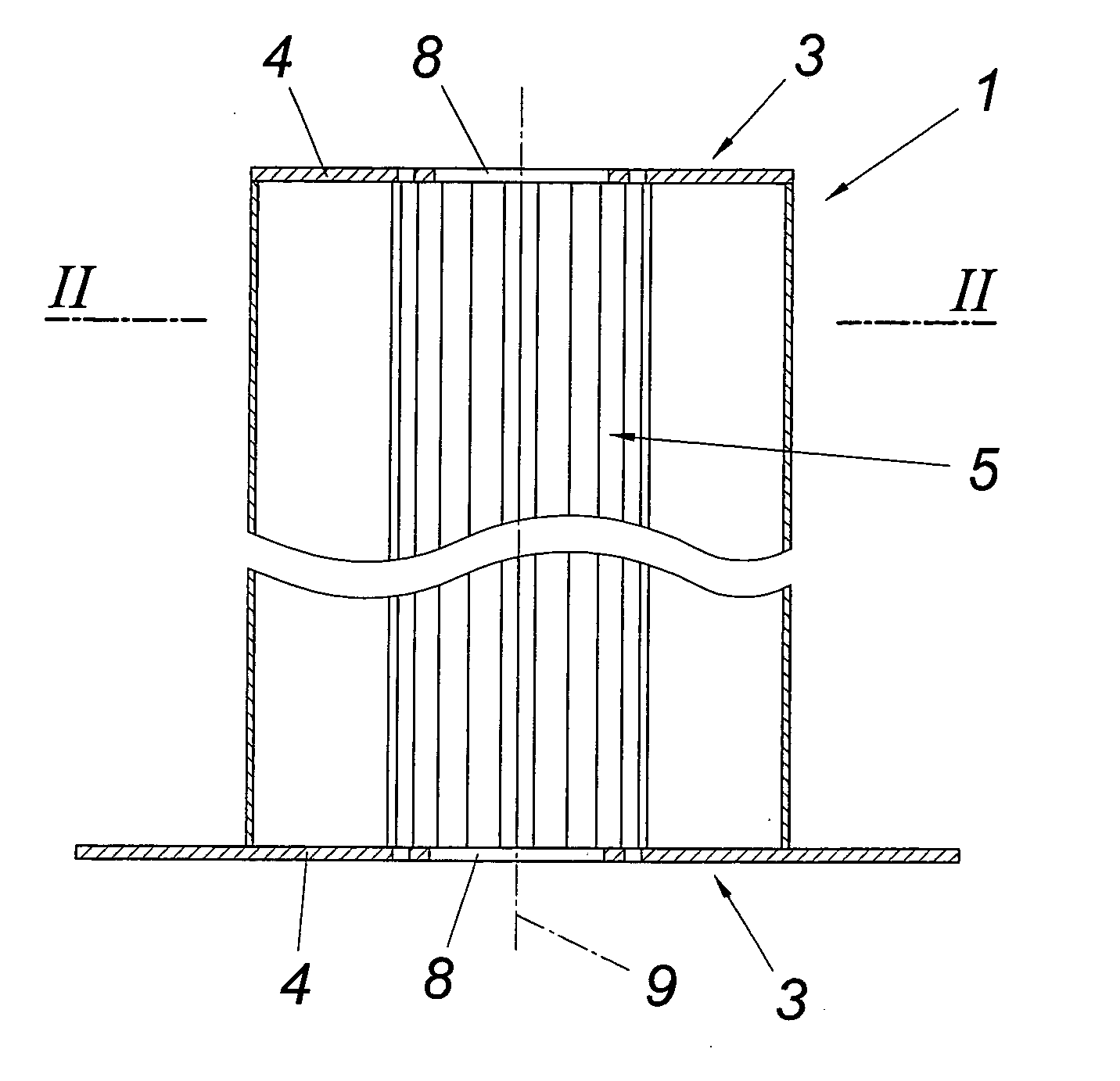
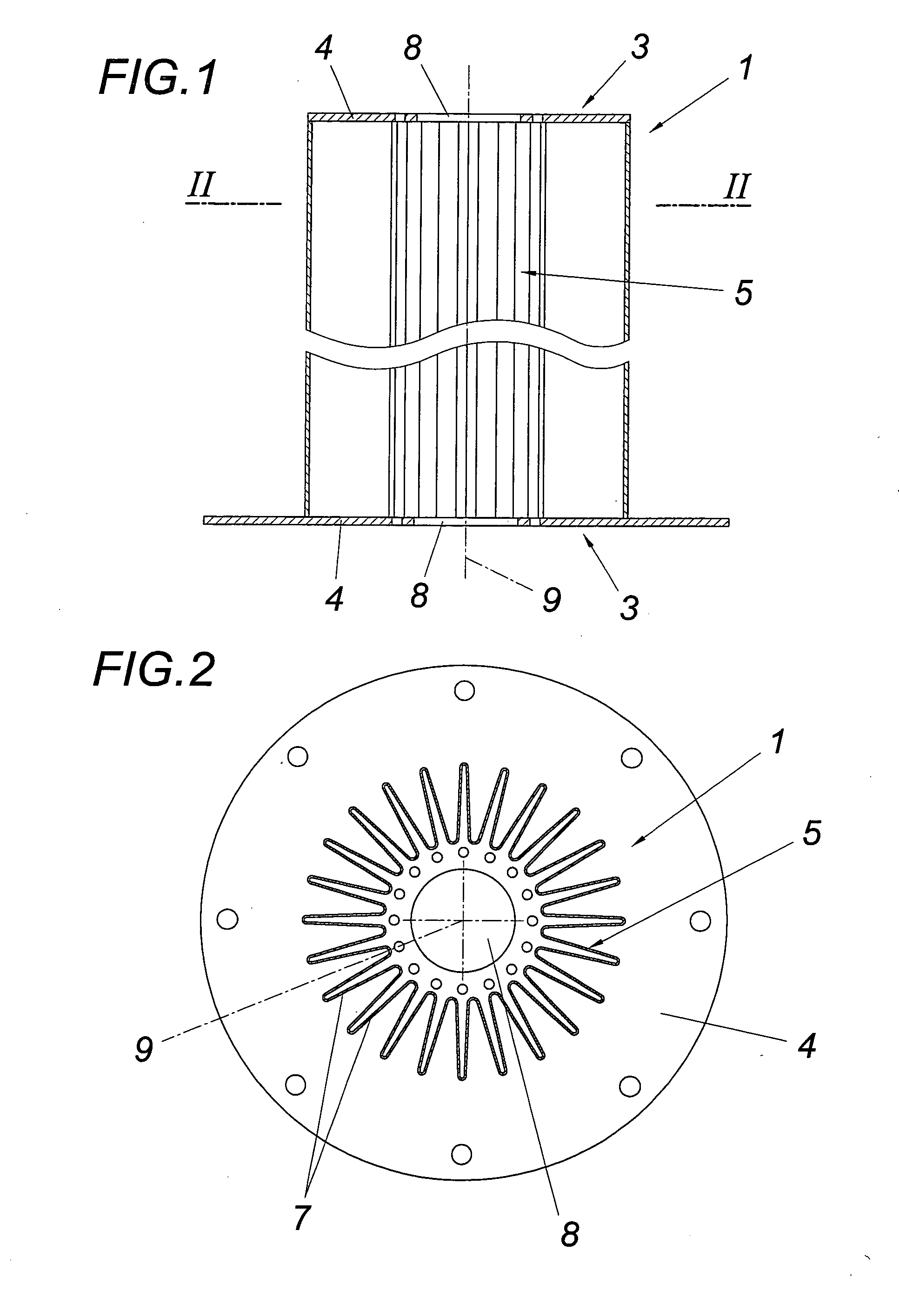
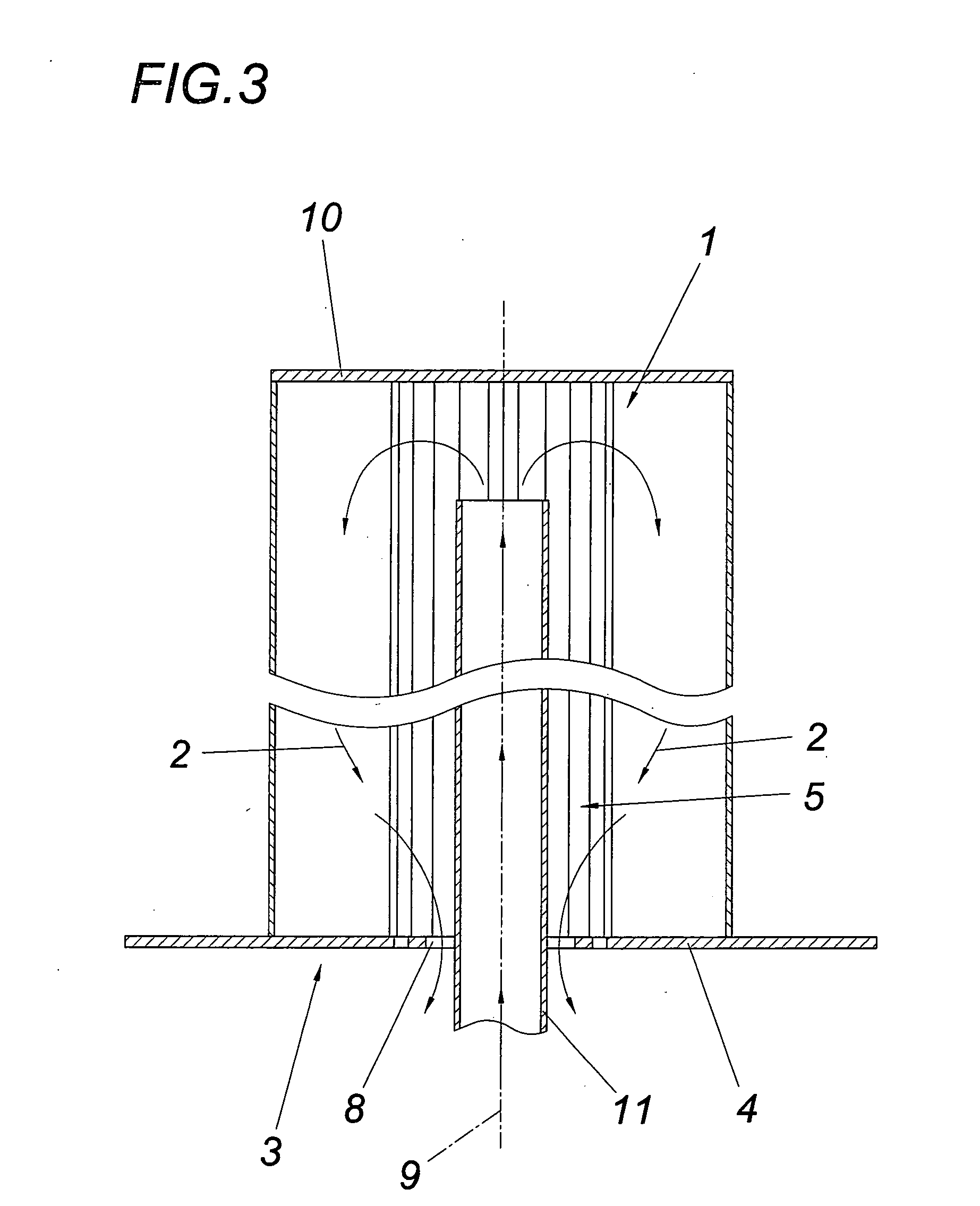
[0015]A heat exchanger 1 for an annealing furnace for the exchange of heat between two fluids, a hot gas 2 flowing through the interior of the heat exchanger and an interior of an annealing furnace to be heated by the heat exchanger comprises on at least one face side 3 a connecting flange 4 with at least one flow opening 8 for one of the two fluids. A flue of a burner can optionally be inserted in said flow opening 8. The heat exchanger 1 is formed by a profile which in accordance with the invention is a profile tube 5 made of folded sheet whose heat exchanger fins 7, which are aligned in the longitudinal direction of the profile tube, parallel to the profile tube axis 6, are formed by the corrugated profile, especially the corrugated flanks, of the folded sheet.

[0016]In accordance with the embodiment according to FIGS. 1 and 2, the profile tube 5 is associated on both face sides with a connecting flange 4 with at least one flow opening 8 each for one of the two fluids which flow t...


PUM

PropertyMeasurementUnit
Flow rateaaaaaaaaaa

Abstract

The invention relates to a heat exchanger (1) for an annealing furnace for exchanging heat between two fluids, comprising a tubular profile which comprises heat exchanger fins on its outside jacket and which is associated on at least one face side (3) with a connecting flange (4) with at least one flow opening (8) for one of the two fluids, especially a hot gas. In order to provide advantageous constructional conditions it is proposed that the profile is a profile tube made of a folded sheet whose heat exchanger fins (7) aligned in the longitudinal direction of the profile are formed by the corrugated profile, especially the corrugated flanks, of the folded sheet.

Description

FIELD OF THE INVENTION[0001]The invention relates to a heat exchanger for an annealing furnace for exchanging heat between two fluids, comprising a tubular profile which comprises heat exchanger fins on its outside jacket and which is associated on at least one face side with a connecting flange with at least one flow opening for one of the two fluids, especially a hot gas.DESCRIPTION OF THE PRIOR ART[0002]In the heat treatment of metallic goods to be annealed, the heat treatment and the optionally necessary subsequent cooling occurs under a protective gas, mostly nitrogen or hydrogen, or a mixture of these gases. In order to ensure a proper protective gas atmosphere which is free from impurities and causes oxidation, the supply and discharge of heat usually occurred previously through high-temperature-resistant heat exchangers made of cast materials or ceramic. Hot gases, especially fuel gases or the like, flow through these heat exchangers or recuperators, with the hot gas passing...

Claims


Application Information

Patent Timeline
IPC IPC(8): F28F1/10
CPCC21D1/00C21D9/00F27B5/14F28F1/16F27D99/0001F28D7/12F27D17/004F28F1/10F28F13/12B21D53/04
Inventor EBNER, PETEREBNER, BRIGITTESAUSCHLAGER, ANDREAS
Owner EBNER-INDUSTRIEOFENBAU GMBH
Why Eureka
Try Eureka