Motor and method of manufacturing the same

a technology of motors and manufacturing methods, applied in the field of motors, can solve the problems of difficult to secure the verticality desired of the bearing housing, complicated assembly process, and conventional spindle motors, and achieve the effect of improving the efficiency of the manufacturing process and reducing the manufacturing cos

Inactive Publication Date: 2011-12-22
SAMHONGSA
View PDF21 Cites 12 Cited by
  • Summary
  • Abstract
  • Description
  • Claims
  • Application Information

AI Technical Summary

Benefits of technology

[0023]Accordingly, the present invention has been made in view of the above problems occurring in the prior art, and it is an object of the present invention to provide a motor in which a bearing housing is made of resin and, at the same time when the bearing housing is made of resin, a base plate is integrated with the bearing housing a method, such as insert

Problems solved by technology

The conventional spindle motor is disadvantageous in that an assembly process is complicated because the connection of the bearing housing 13 and the base plate 11 and the connection of the bearing housing 13 and the cap 15 are performed by a process of spinning or caulking the o

Method used


Image

  • Motor and method of manufacturing the same
  • Motor and method of manufacturing the same
  • Motor and method of manufacturing the same

Examples


first embodiment

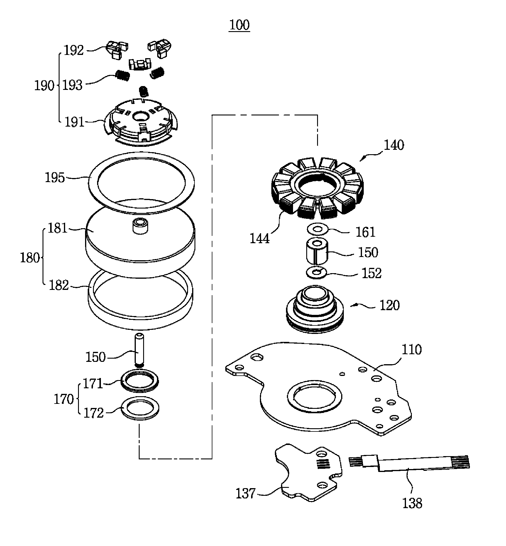
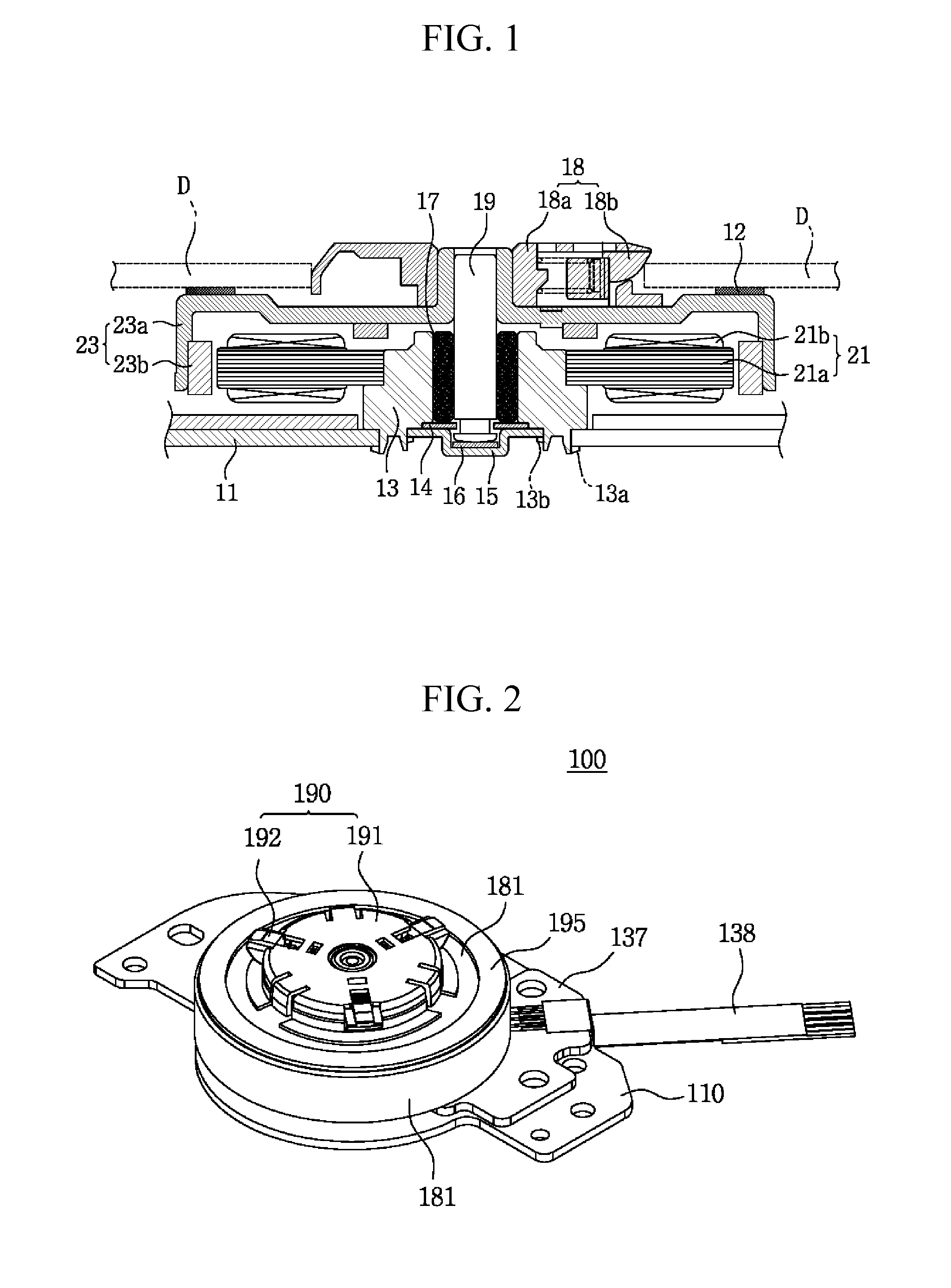
[0048]FIGS. 2 to 6 are a perspective view, a bottom view, a cross-sectional view, an exploded perspective view, and a perspective view showing an ultra-thin type spindle motor according to the present invention.

[0049]Referring to FIGS. 2 to 6, the ultra-thin type spindle motor 100 according to the first preferred embodiment of the present invention chiefly includes a stator (or an armature) 140 and a rotor 180 of an outer rotor method.

[0050]First, the stator 140 includes a core 141 configured to have a plurality of teeth 144 protruded in a radial direction from the body of a ring shape, a bobbin 142 made of insulating material in each of the teeth, and a coil 143 wound on the outside of the bobbin 142.

[0051]The rotor 180 includes a rotor casing 181 formed in a reversed cup shape and a ring-shaped magnet 182 configured to have a plurality of N pole and S pole magnets alternately disposed or the N poles and the S poles divided and magnetized thereon. In this case, it is preferred that...

second embodiment

[0085]A spindle motor 100a according to the present invention is described below with reference to FIG. 9.

[0086]In the spindle motor 100 according to the first embodiment of the present invention, when the stator 140 is assembled with the bearing housing 120, the stator 140 is pressed and connected to the outer circumference of the third outer diameter portion 127 and then fixed using adhesives. Furthermore, the york 172 of a ring shape is connected to the outer circumference of the fourth outer diameter portion 128 and then fixed using adhesives.

[0087]In the spindle motor 100a according to the second embodiment, a plurality of fixing protrusions 127a is formed at specific intervals from a step portion 128a between the third outer diameter portion 127 and the fourth outer diameter portion 128 of the bearing housing 120 to the upper side. A plurality of through holes 172b corresponding to the respective fixing protrusions 127a is formed in the york 172 of a ring shape. A plurality of...

sixth embodiment

[0093]In a spindle motor 100e shown in FIG. 15, at least one, preferably, four assembly guides 127b are integrally formed at specific intervals on the outer circumference of the third outer diameter portion 127 of the bearing housing 120. A plurality of assembly concave grooves 141a corresponding to the assembly guides 127b is formed on the inner circumference of the stator 140 connected to the assembly concave grooves 141a.

[0094]In the spindle motor 100e according to the sixth embodiment, when the stator 140 is fixed to the bearing housing 120, the stator 140 can be assembled with the bearing housing 120 at a constant position using the plurality of assembly guides 127b provided on the outer circumferential portion of the bearing housing 120, and the rotation of the assembled stator 140 can be prevented.

[0095]On the other hand, at least one, preferably, a plurality of assembly guides may be provided on the inner circumference of the stator 140, and a plurality of assembly concave...


PUM

PropertyMeasurementUnit
Weightaaaaaaaaaa
Diameteraaaaaaaaaa
Speedaaaaaaaaaa

Abstract

The present invention relates to a motor, particularly, to a spindle motor and a method of manufacturing the same, in which a base plate is integrated with a bearing housing an insert molding or insert injection method at the same time when the bearing housing is made of resin, thereby being capable of securing the verticality of a bearing and a pivot assembled with the bearing housing and the base plate, reducing the manufacturing cost, and improving the efficiency of a manufacturing process. The motor of the present invention includes a rotor, a pivot configured to have one end connected to the rotor, a bearing configured to rotatably support the outer circumferential face of the pivot, and a bearing housing made of resin and configured to comprise a first concave groove for receiving the bearing and a second concave groove for supporting the other end of the pivot.

Description

CROSS-REFERENCE TO RELATED APPLICATION[0001]Priorities to Korean patent application numbers 10-2010-0058073 filed on Jun. 18, 2010 and 10-2010-0111375 filed on Nov. 10, 2010, the entire disclosure of which is incorporated by reference herein, is claimed.BACKGROUND OF THE INVENTION[0002]1. Field of the Invention[0003]The present invention relates to a motor and a method of manufacturing the same and, more particularly, to a motor in which a bearing housing is made of resin and, at the same time when the bearing housing is made of resin, a base plate is integrated with the bearing housing a method, such as insert injection, heat fusion, or bonding, thereby being capable of securing the verticality of a bearing and a pivot assembled with the bearing housing and the base plate, reducing the manufacturing cost, improving the efficiency of a manufacturing process, and particularly applicable to a spindle motor for high-speed rotation, and a method of manufacturing the motor.[0004]2. Backg...

Claims


Application Information

Patent Timeline
IPC IPC(8): H02K5/167H02K15/14
CPCG11B19/2009H02K1/187Y10T29/49009H02K2203/03H02K11/0073H02K11/33
Inventor MIN, BYUNG SUNGLEE, JONG HOON
Owner SAMHONGSA
Why Eureka
Try Eureka