
MEMS microphone and manufacturing method thereof

Inactive Publication Date: 2011-12-22
BSE CO LTD
View PDF1 Cites 22 Cited by
  • Summary
  • Abstract
  • Description
  • Claims
  • Application Information

AI Technical Summary

Benefits of technology

[0017]According to embodiments of the present invention, a contact-preventing electrode unit applies repulsive force to a membrane. Therefore, even if an excessive voltage or an external shock is applied to the membrane, the membrane and the back plate may be prevented from contacting each other.
[0018]According to embodiments of the present invention, it is not necessary to heat a membrane and a back plate to a high temperature to implant ions into the membrane and the back plate, and formation of residual stress in the membrane and the back plate may be minimized. Furthermore, formation of cracks in areas where the membrane and the back plate contact a silicon substrate may be prevented
[0019]According to embodiments of the present invention, since a membrane and a back plate are formed via eletroless plating, thicknesses of the membrane and the back plate may be easily controlled. Therefore, acoustic properties may be stabilized and acoustic sensitivity may be improved.

Problems solved by technology

Therefore, the costs for manufacturing the condenser microphone are high, and there are limits in miniaturizing the condenser microphone.
Thus, the membrane may be deformed or cracked due to the residual stress applied thereto.
Furthermore, when the residual stress is applied to the membrane, it may be diffiult for the membrane to precisely oscillate according to sounds, and thus, it may be difficult to precisely convert sounds to electric signals.
Furthermore, the rate of oxidating silicon of the porous silicon structure may become nonuniform according to a voltage condition, and thus, the back side may be etched unevenly.
If a surface of the back side is unevenly etched, a distance between a diaphragm and a back plate becomes uneven, and thus, it may be difficult to precisely convert sounds to electric signals.
Therefore, it is difficult to manufacture the MEMS chip and the ASIC as one chip.
The reason is that, when the ASIC is exposed to a high temperature in a process for manufacturing the MEMS chip, the circuit patterned onto the ASIC melts or is damaged.
Furthermore, since it is difficult to manufacture the MEMS chip and the ASIC as one chip, it is necessary to manufacture the MEMS chip and the ASIC via separate processes.
Therefore, the number of manufacturing processes and manufacturing costs may increase.
Furthermore, according to the cited references above, the membrane and the bottom electrode may contact each other when an excessive voltage or an external shock is applied to the membrane or the bottom electrode.
Therefore, there may be cases in which it is difficult to convert sounds to electric signals.

Method used


Image

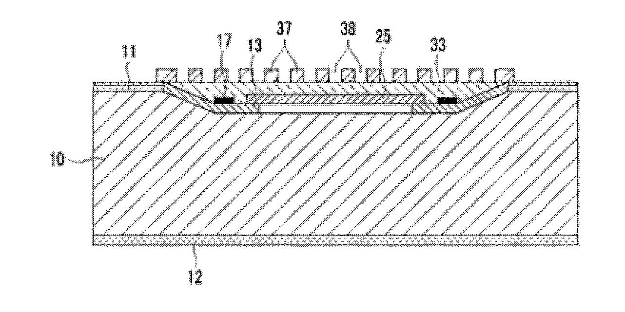
  • MEMS microphone and manufacturing method thereof
  • MEMS microphone and manufacturing method thereof
  • MEMS microphone and manufacturing method thereof

Examples


Embodiment Construction

[0032]Hereinafter, the present invention will be described in detail by explaining preferred embodiments of the invention with reference to the attached drawings.

[0033]A micro electro mechanical system (MEMS) microphone according to an embodiment of the present invention will be described below.

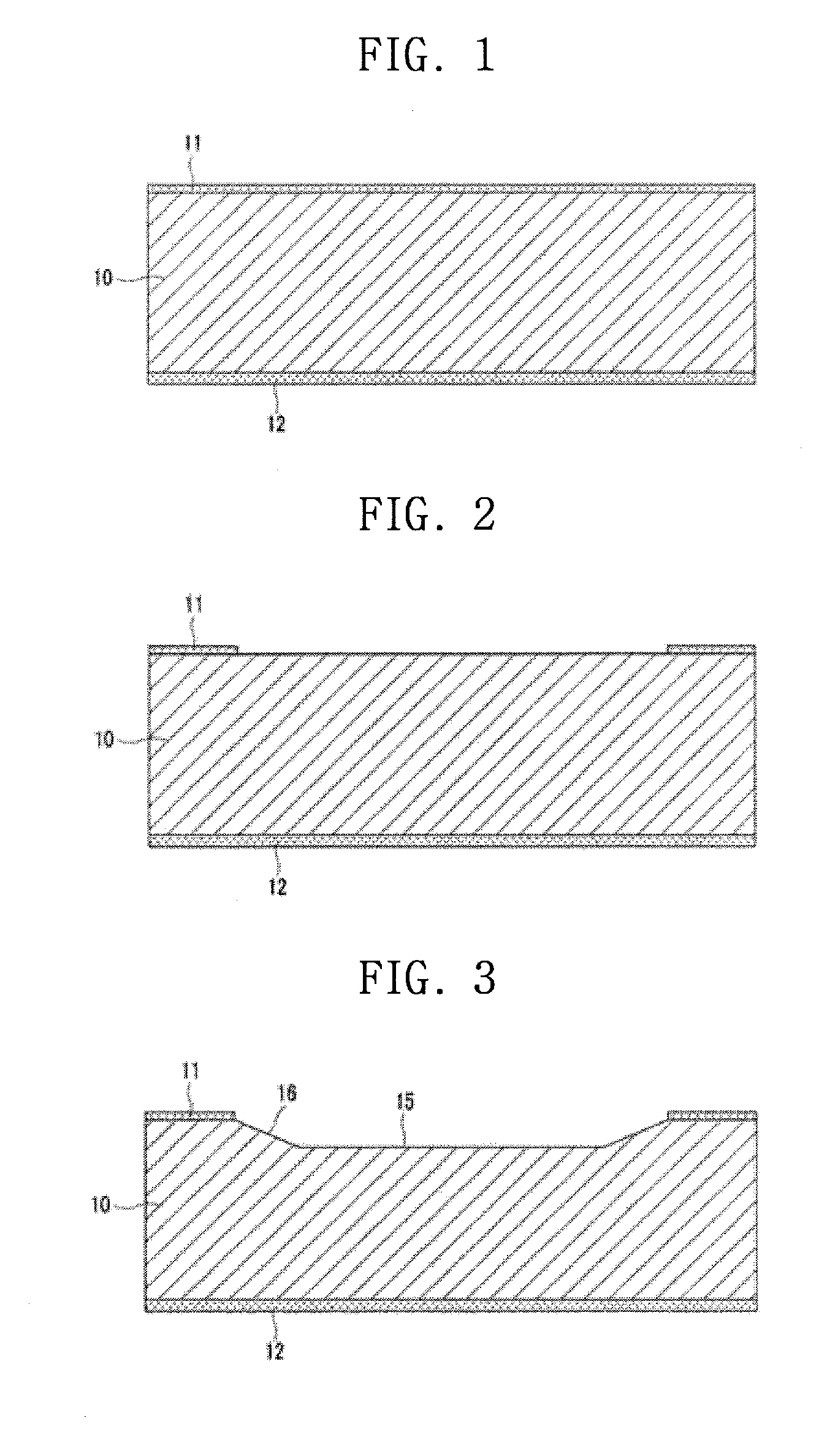
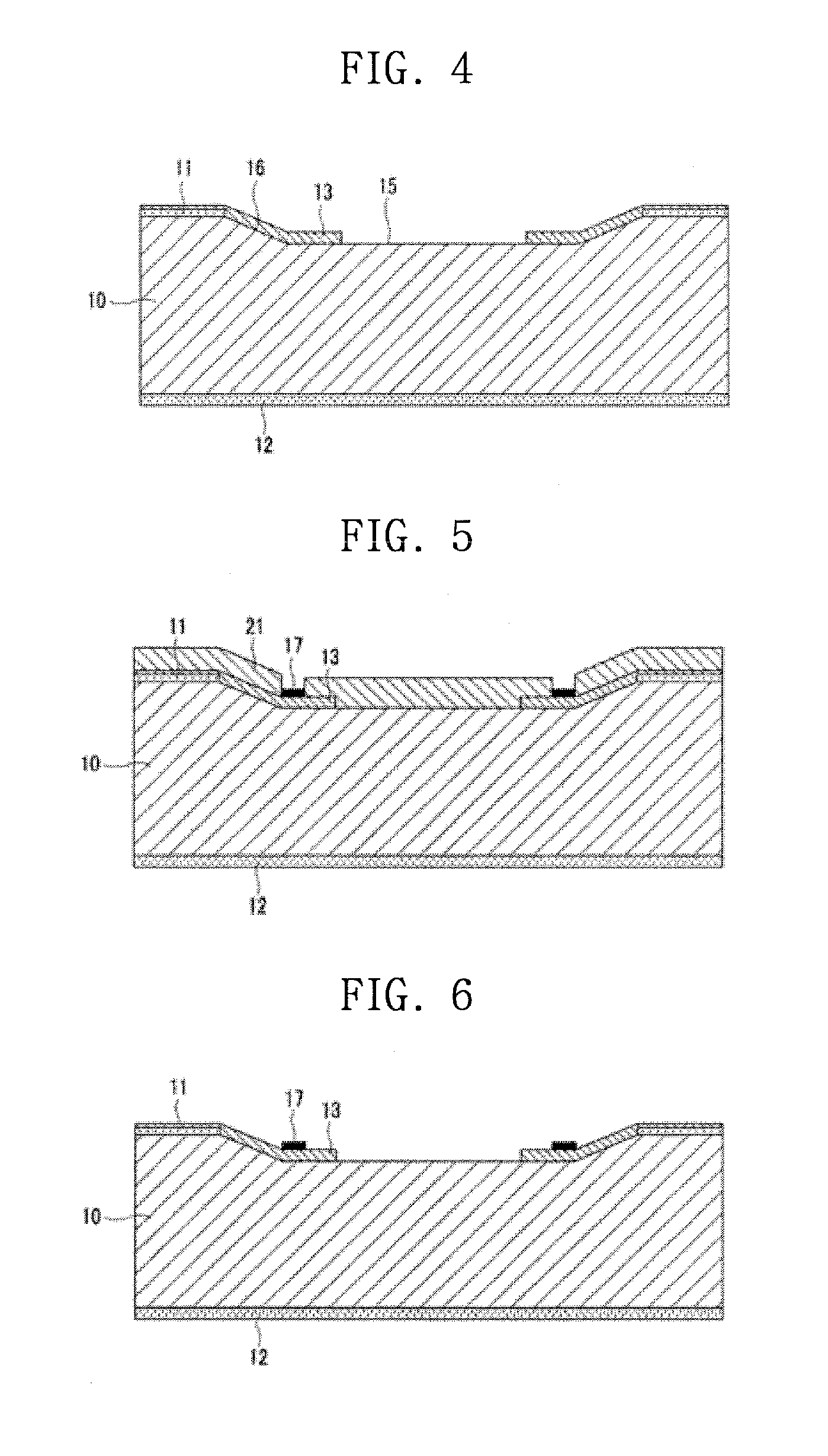
[0034]FIGS. 1 through 3 are sectional views showing operations for forming an air gap forming portion in a silicon substrate according to an embodiment of the present invention.

[0035]Referring to FIGS. 1 and 2, the MEMS microphone includes a silicon substrate 10. Insulation protection layers 11 and 12, formed of silicon nitride (SiN2) or silicon oxide (SiO2), for example, are formed on both surfaces of the silicon substrate 10 (refer to FIG. 1). Here, in the case of the silicon nitride, the insulation protection layers 11 and 12 are formed on surfaces of the silicon substrate 10 by using low pressure chemical vapor deposition (LPCVD).

[0036]The insulation protection layer 11 on the top surface...


PUM


Abstract

A micro electro mechanical system (MEMS) microphone capable of preventing a membrane and a back plate from being contacting each other by an overvoltage, an external shock, and the like, and a method of manufacturing the MEMS microphone. The MEMS microphone includes a silicon substrate in which a back chamber is to be formed; a back plate which is formed on the silicon substrate and has formed therein a plurality of sound holes; a membrane which is formed on the silicon substrate at a predetermined distance apart from the back plate to form an air gap; and a contact-preventing electrode unit which is formed on the silicon substrate and applies a repulsive force to the membrane.

Description

TECHNICAL FIELD[0001]The present invention relates to a micro electro mechanical system (MEMS) microphone and a method of manufacturing the same.BACKGROUND ART[0002]Generally, a microphone is a device for converting sounds to electric signals. The microphone may be used in various mobile communication devices, such as mobile phones, and various communication devices including earphones and hearing aids. It is necessary for the microphone to have excellent electronic / sound performance, reliability, and operability.[0003]Microphones may be classified into condenser microphones and micro electro mechanical system (MEMS) microphones.[0004]A condenser microphone is manufactured by manufacturing each component, such as a diaphragm, a back plate, and a printed circuit board (PCB) for signal processing, and assembling the components inside a casing. The condenser microphone is manufactured via two separate processes, that is, a process for fabricating a PCB and a process for manufacturing t...

Claims


Application Information

Patent Timeline
IPC IPC(8): H04R1/00H01L21/02
CPCB81B7/0016B81C1/00976H04R19/04H04R31/00B81B2203/0109H04R19/005B81B2201/0257H04R3/007H04R19/00
Inventor KIM, YONG-KOOK
Owner BSE CO LTD
Learn More