Mass Spectrometer

a mass spectrometer and mass spectrometer technology, applied in the field of mass spectrometers, can solve the problems of inability to precisely, impede the accuracy of analysis, and the process is very labor-intensive and time-consuming, so as to reduce labor and time, and perform efficiently

Inactive Publication Date: 2011-12-29
SHIMADZU CORP
View PDF11 Cites 8 Cited by
  • Summary
  • Abstract
  • Description
  • Claims
  • Application Information

AI Technical Summary

Benefits of technology

[0031]With a mass spectrometer according to the present invention, a measurement region to be subjected to mass spectrometry can be decided based on specimen observation images of a high spatial resolution and covering a region that is larger than microscopic observation images that are obtained by high-magnification factor microscopic observation. This means that even when performing a two-dimensional mass spectrometry on a large region on a specimen or on the entire specimen, there is no need to repeat the steps of setting the measurement region by microscopic observation and performing mass spectrometry, allowing mass spectrometry imaging over a large area to be performed efficiently, thus reducing labor and time required. Furthermore, since the mass spectrometry images that are divided and acquired need not be joined together, mass spectrometry images that are superior to previous ones are obtained.

Problems solved by technology

With previous mass microscopes, it is not possible to precisely analyze in a single pass a region that extends beyond the observation field of a microscope and obtain a mass spectrometry image, When a measurement of that sort is required, the steps of specifying a measurement region on a microscopic observation image that is obtained with a microscope using a high magnification factor and then performing mass spectrometry on the specified measurement region have to be repeated multiple times while incrementally moving the specimen and shifting the observation field.
This process is very labor-intensive and time-consuming.
Furthermore, when working with biological specimens, if the measurement time becomes protracted, the specimen itself may undergo changes in its dynamic behavior or metamorphose and may hamper an accurate analysis.
Furthermore, with the afore-described method involving the repetition of microscopic observation and mass spectrometry, there is no guarantee for the continuity or the precision of the positional relationship between a measurement region that is present on a specimen and other measurement regions that are supposed to be adjacent to it.

Method used


Image

  • Mass Spectrometer
  • Mass Spectrometer
  • Mass Spectrometer

Examples


Embodiment Construction

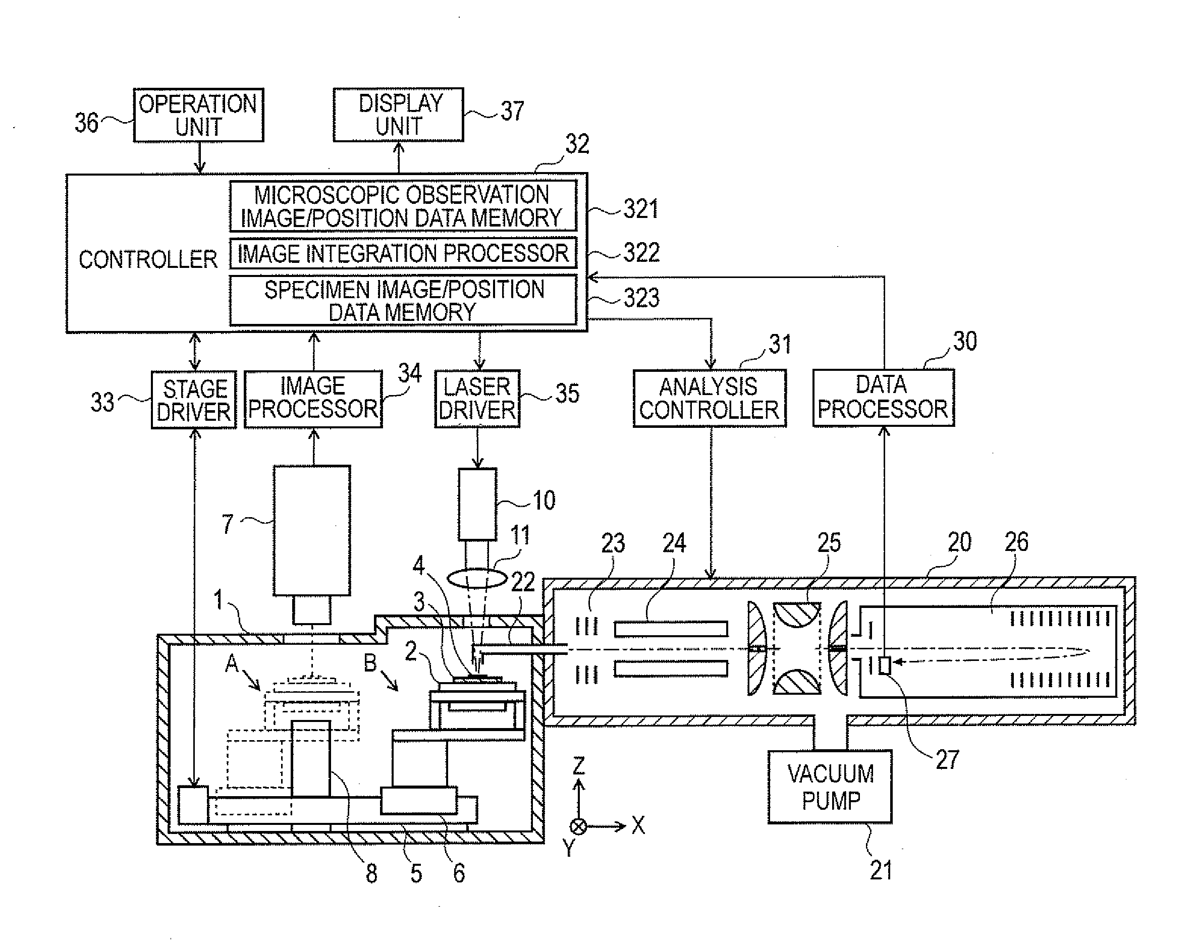
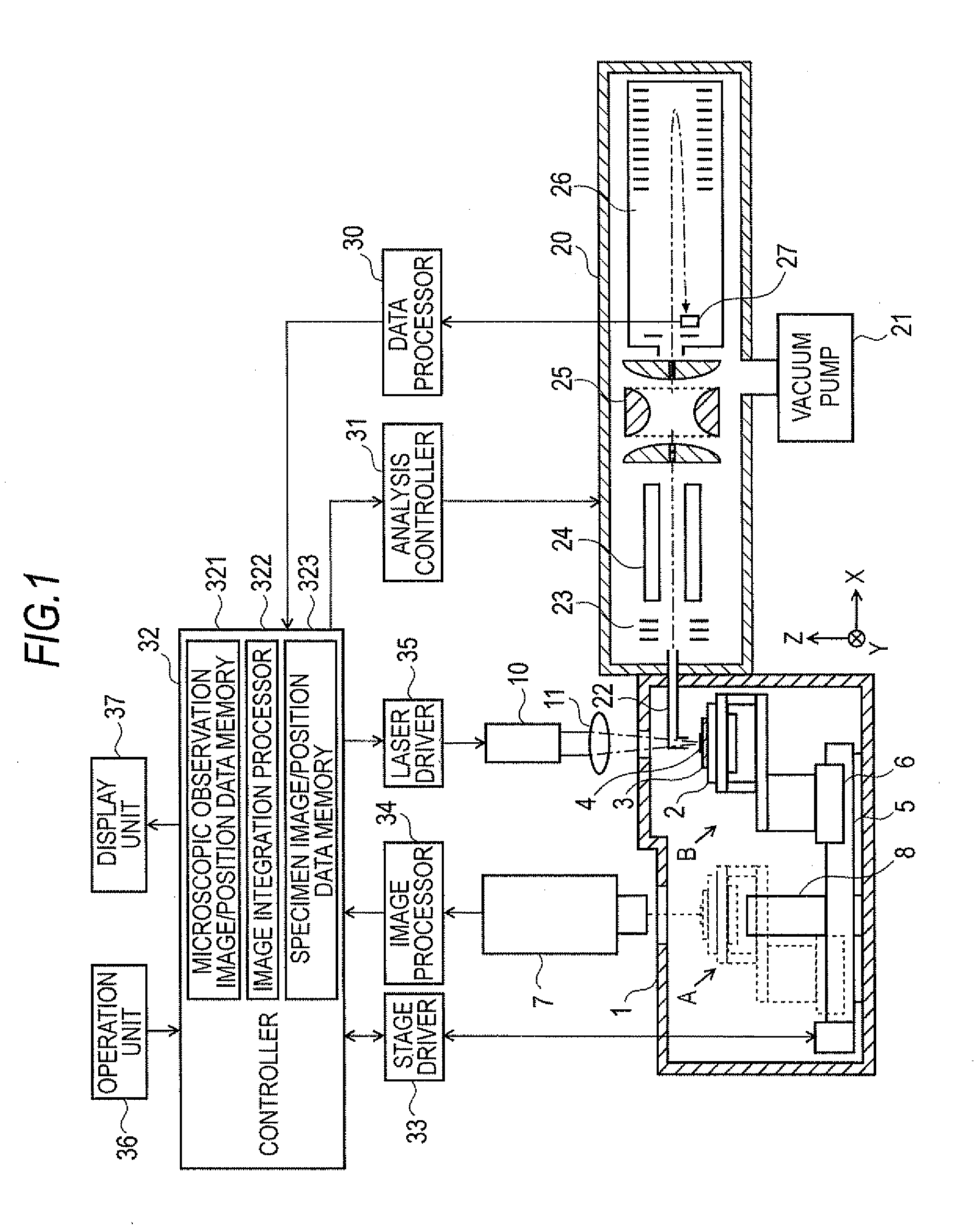
[0065]As one embodiment of a mass spectrometer according to the present invention, a mass microscope is described next with reference to FIGS. 1 through 5. FIG. 1 shows the overall configuration of the present embodiment as a mass microscope.

[0066]The mass microscope has a sealed chamber 1 whose internals are maintained substantially at atmospheric pressure, a vacuum chamber 20 whose internal atmosphere is kept at a high level of vacuum by means of a vacuum pump 21 such as a turbo molecular pump. Disposed within the sealed chamber 1 is specimen stage 2 which holds specimen plate 3 upon which specimen 4 is placed. A drive mechanism 6 that includes a motor and the like can drive the specimen stage 2 in a sliding reciprocal motion that covers a large distance in the X-direction along guide 5. In FIG. 1, the position where specimen stage 2 is depicted with the solid lines is identified as analysis position B. Where the position is identified by dotted lines shows observation position A....


PUM


Abstract

When specimen (4) is placed on specimen stage (2), controller (32)—via the stage driver (33) and drive mechanism (6)—moves the specimen stage (2) by a predetermined step pitch according to the magnification factor in the X-direction and the Y-direction, and the image pickup unit (7) acquires a microscopic observation image of the specimen (4) after each move. The microscopic observation image that is acquired and the position data of the specimen stage (2) when the image is acquired are stored in memory (321). When a plurality of microscopic observation images of the areas that are adjacent on the specimen (2) are obtained, the image integration processor (322) uses the position data to join the microscopic observation images. When a plurality of microscopic observation images that encompasses the entirety of the specimen (2) is all joined together to form a specimen observation image, the specimen observation image is displayed on a display unit 37. The user then specifies the desired measurement region based on the specimen observation image that is high in spatial resolution and covering a wide area. Because of this, there is no need to repeat the steps of image pickup and mass spectrometry even when performing a mass spectrometry over a wide area, allowing an efficient measurement.

Description

TECHNICAL FIELD[0001]The present invention relates to mass spectrometers and, in particular, to mass spectrometers referred to as mass microscopes or imaging mass spectrometers which are capable of performing mass spectrometry on a two-dimensional region of a specimen.BACKGROUND ART[0002]Apparatuses referred to as mass microscope and imaging mass spectrometer have been developed to observe the morphology of specimens such as biological tissues and, at the same time, measure the distribution of molecules that are present in a predetermined region of the specimen (see Patent Literature 1 through 3 and Non-Patent Literature 1 and 2). With these apparatuses, without crushing or pulverizing a specimen as required previously and hence while substantially preserving the morphology of the specimen, an image showing the distribution of ions having a specific mass (more precisely, having a specific mass / charge ratio, m / z) present in an optional area that is specified on the specimen by micros...

Claims


Application Information

Patent Timeline
Patent Type & Authority Applications(United States)
IPC IPC(8): H01J49/26
CPCG01N27/628H01J49/0413H01J49/0004
Inventor IKEGAMI, MASAHIROOGAWA, KIYOSHIHARADA, TAKAHIRO
Owner SHIMADZU CORP
Why Eureka
Try Eureka