
Solid Electrolytic Capacitor Containing an Improved Manganese Oxide Electrolyte

a technology of solid electrolytic capacitor and manganese oxide, which is applied in the manufacture of electrolytic capacitors, variable capacitors, electrolytic capacitors, etc., can solve the problems of poor electrical performance, and large amount of manganese dioxid

Active Publication Date: 2011-12-29
KYOCERA AVX COMPONENTS CORP
View PDF1 Cites 4 Cited by
  • Summary
  • Abstract
  • Description
  • Claims
  • Application Information

AI Technical Summary

Benefits of technology

In accordance with one embodiment of the present invention, a solid electrolytic capacitor is disclosed that comprises an anode body formed from an electrically conductive powder, wherein the powder has a specific charge of about 70,000 μF*V...

Problems solved by technology

To achieve the desired thickness of the solid electrolyte, the steps of immersion and heating are often repeated multiple times. Unfortunately, one problem with conventional manganizing techniques is that the thickness of the resulting manganese dioxide is often greater at certain locations of the anode (e.g., edges), which can lead to poor electrical performance.
Although the addition of surfactants may provide some benefits, significant problems nevertheless remain.
For example, the capacitors may still exhibit a relatively large loss in capacitance when wet and a high leakage current.
This problem is particularly evident when the valve metal powder used to form the anode has a high specific charge—i.e., about 70,000 microFarads*Volts per gram (“μF*V / g”) or more.
Such high “CV / g” powders are generally formed from particles having a small size and large surface area, which results in the formation of small pores between the particles that are difficult to impregnate with the manganese nitrate solution.
The difficulty in impregnating such small pores leads to the formation of manganese dioxide particles that are large in size and irregularly shaped.
These particles do not adhere well to the dielectric coating and are unable to achieve good surface coverage, which leads to poor electrical performance of the capacitor.

Method used

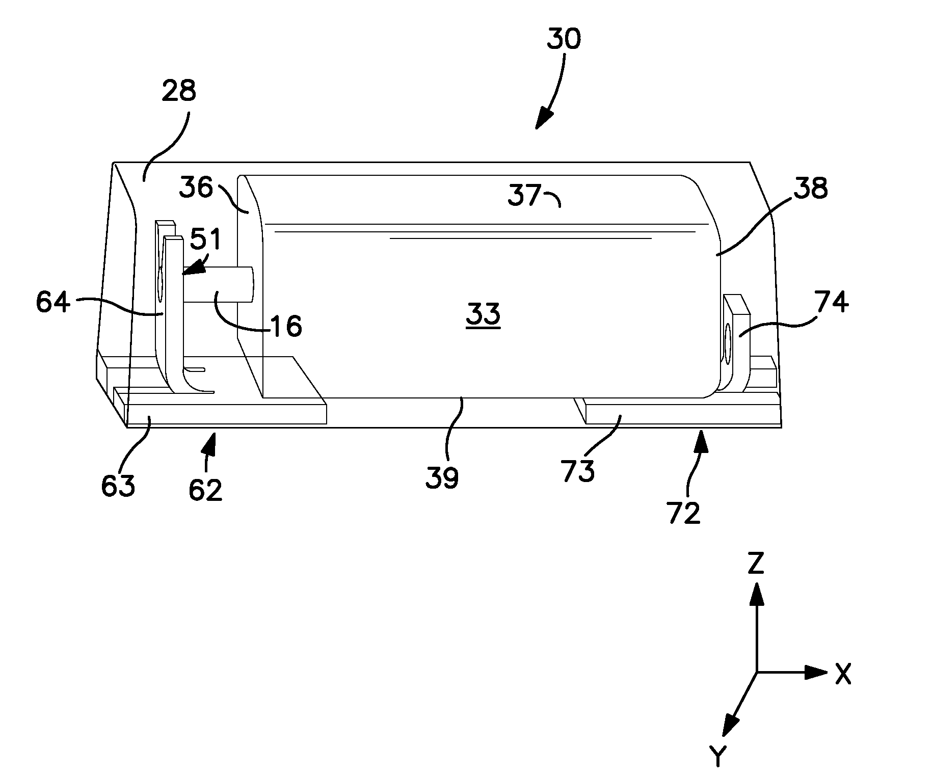
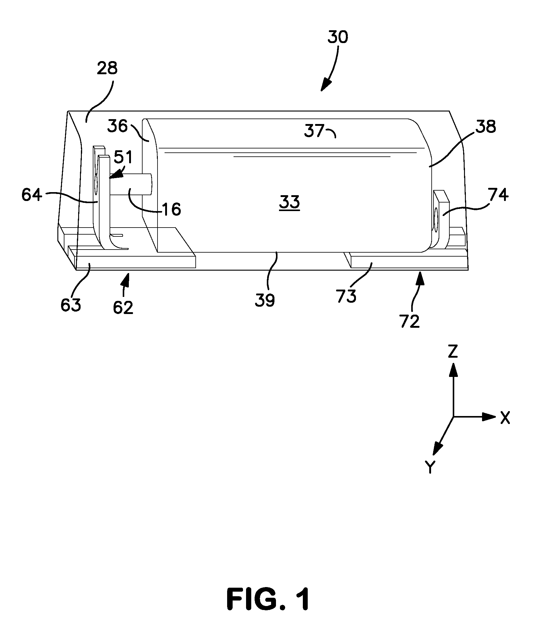
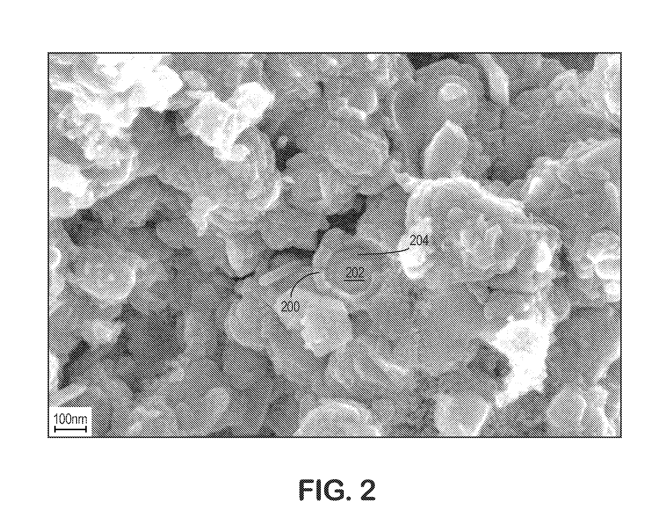

Image

  • Solid Electrolytic Capacitor Containing an Improved Manganese Oxide Electrolyte
  • Solid Electrolytic Capacitor Containing an Improved Manganese Oxide Electrolyte
  • Solid Electrolytic Capacitor Containing an Improved Manganese Oxide Electrolyte

Examples


example 1

150,000 μF*V / g Tantalum Powder (Capacitors 100 μF / 4V)

Initially, 3×100,000 capacitor element samples were formed from tantalum anodes having a size of 1.65 mm (length)×1.15 mm (width)×0.85 mm (thickness). Each anode was embedded with a tantalum wire, pressed to a density of 5.85 g / cm3, and sintered at 1270° C. for 20 minutes. The tantalum anode was anodized in an orthophosphoric acid / water solution having a conductivity of 8.6 mS / cm and temperature of 85° C. with a forming voltage of 11 volts. The samples were initially dipped into an aqueous solution of manganese(II) nitrate (1150 kg / m3) for 150 seconds and then decomposed at 250° C. to achieve the MnO2 electrolyte. This step was repeated eight times.

Thereafter, a first set of samples was dipped into an aqueous solution of manganese(II) nitrate (1300 kg / m3) and 3 g / dm3 of a dispersant (Spolostan 4P, a sodium salt of naphthalene sulfonic acid, polymerized with formaldehyde and produced in Enaspol, Czech Republic), and then decomposed...

example 2

70,000 μF*V / g Tantalum Powder (Capacitors 220 μF / 6.3V)

Initially, 2×100,000 capacitor element samples were formed from tantalum anodes having a size of 1.8 mm (length)×2.45 mm (width)×1.35 mm (thickness). Each anode was embedded with a tantalum wire, pressed to a density of 6.1 g / cm3, and sintered at 1295° C. for 20 minutes. The tantalum anode was anodized in an orthophosphoric acid / water solution having a conductivity of 8.6 mS / cm and temperature of 85° C. with a forming voltage of 9 volts. The samples were dipped into a conventional aqueous solution of manganese(II) nitrate (1050 kg / m3) for 150 seconds and then decomposed at 250° C. This step was repeated two times. Next, the samples were dipped into a conventional aqueous solution of manganese(II) nitrate (1150 kg / m3) for 150 seconds and then decomposed at 250° C. This step was repeated eight times. Thereafter, a first set of samples was dipped into an aqueous solution of manganese(II) nitrate (1300 kg / m3) and 3 g / dm3 of Spolostan...

example 3

80,000 μF*V / g Niobium Oxide Powder (Capacitors 220 μF / 6.3V)

Initially, 3×20,000 capacitor element samples were formed from NbO anodes having a size of 3.5 mm (length)×2.7 mm (width)×1.65 mm (thickness). Each anode was embedded with a tantalum wire, pressed to a density of 3.1 g / cm3, and sintered at 1460° C. for 20 minutes. The NbO anodes were anodized in an orthophosphoric acid / water solution having a conductivity of 8.6 mS / cm and temperature of 85° C. with a forming voltage of 15V. The samples were dipped into a conventional aqueous solution of manganese(II) nitrate (1150 kg / m3) for 150 seconds and then decomposed at 200° C. This step was repeated six times. Thereafter, a first set of samples was dipped into an aqueous solution of manganese(II) nitrate (1300 kg / m3) and 3 g / dm3 of Spolostan 4P and then decomposed at 200° C. This step was repeated two times. A second set of the samples was dipped into an aqueous solution of manganese(II) nitrate (1300 kg / m3) and 3 g / dm3 of Erkantol NR...


PUM

PropertyMeasurementUnit
Temperatureaaaaaaaaaa

Abstract

A solid electrolytic capacitor that contains an anode body formed from an electrically conductive powder and a dielectric coating located over and / or within the anode body is provided. The powder has a high specific charge and in turn a relative dense packing configuration. Despite being formed from such a powder, the present inventors have discovered that a manganese precursor solution (e.g., manganese nitrate) can be readily impregnated into the pores of the anode. This is accomplished, in part, through the use of a dispersant in the precursor solution that helps minimize the likelihood that the manganese oxide precursor will form droplets upon contacting the surface of the dielectric. Instead, the precursor solution can be better dispersed so that the resulting manganese oxide has a “film-like” configuration and coats at least a portion of the anode in a substantially uniform manner. This improves the quality of the resulting oxide as well as its surface coverage, and thereby enhances the electrical performance of the capacitor.

Description

BACKGROUND OF THE INVENTIONManganese dioxide is known and widely used as a solid electrolyte in electrolyte capacitors. Such capacitors are conventionally formed by first anodizing a valve-metal anode (e.g., tantalum) to form a dielectric oxide coating, and thereafter immersing the oxide-coated anode in an aqueous solution of manganese nitrate. After a sufficient period of time, the wet anode is heated to cause pyrolytic decomposition of the manganese nitrate to manganese dioxide. To achieve the desired thickness of the solid electrolyte, the steps of immersion and heating are often repeated multiple times. Unfortunately, one problem with conventional manganizing techniques is that the thickness of the resulting manganese dioxide is often greater at certain locations of the anode (e.g., edges), which can lead to poor electrical performance. Various techniques have been employed in an attempt to address these problems. For example, surfactants have been employed in the manganese nitr...

Claims


Application Information

Patent Timeline
IPC IPC(8): H01G9/02H01G7/00H01G9/00H01G9/004H01G9/032H01G9/04H01G9/052
CPCH01G9/0036H01G9/032H01G9/15B82Y99/00Y10T29/435H01G9/042Y10S977/948Y10T29/417H01G9/025H01G9/0525
Inventor PINWILL, IANMASHEDER, DAVIDVILCOVA, SILVIESTOJAN, PETRHURT, JIRIHORACEK, IVAN
Owner KYOCERA AVX COMPONENTS CORP
Learn More