Near-field optical microscope, near-field optical probe, and sample observation method

a sample observation method and near-field optical microscope technology, applied in the direction of instruments, lenses, material analysis by optical means, etc., can solve the problems of difficult detection of light, image cannot be observed with a conventional optical microscope, and difficulty in light detection

Inactive Publication Date: 2011-12-29
OLYMPUS CORP +1
View PDF2 Cites 25 Cited by
  • Summary
  • Abstract
  • Description
  • Claims
  • Application Information

AI Technical Summary

Benefits of technology

[0025]a light shielding member having an apertur

Problems solved by technology

Accordingly, there is a fear that the evanescent light that has been leaked into the near-field optical probe be attenuated by such media disposed on the way to the photodetector, making it difficult to perform the detection of the light.
Accordingly, if the evanescent light, which has already been reduced as described above, is further attenuated before reaching the photodetector, the detection of the light becomes difficult.
Meanwhile, an image to be obtained by the above-mentioned superlens or by the above-mentioned anisotropic medium contains information having a high spatial frequency which turns into an evanescent wave in vacuum,

Method used


Image

  • Near-field optical microscope, near-field optical probe, and sample observation method
  • Near-field optical microscope, near-field optical probe, and sample observation method
  • Near-field optical microscope, near-field optical probe, and sample observation method

Examples


first embodiment

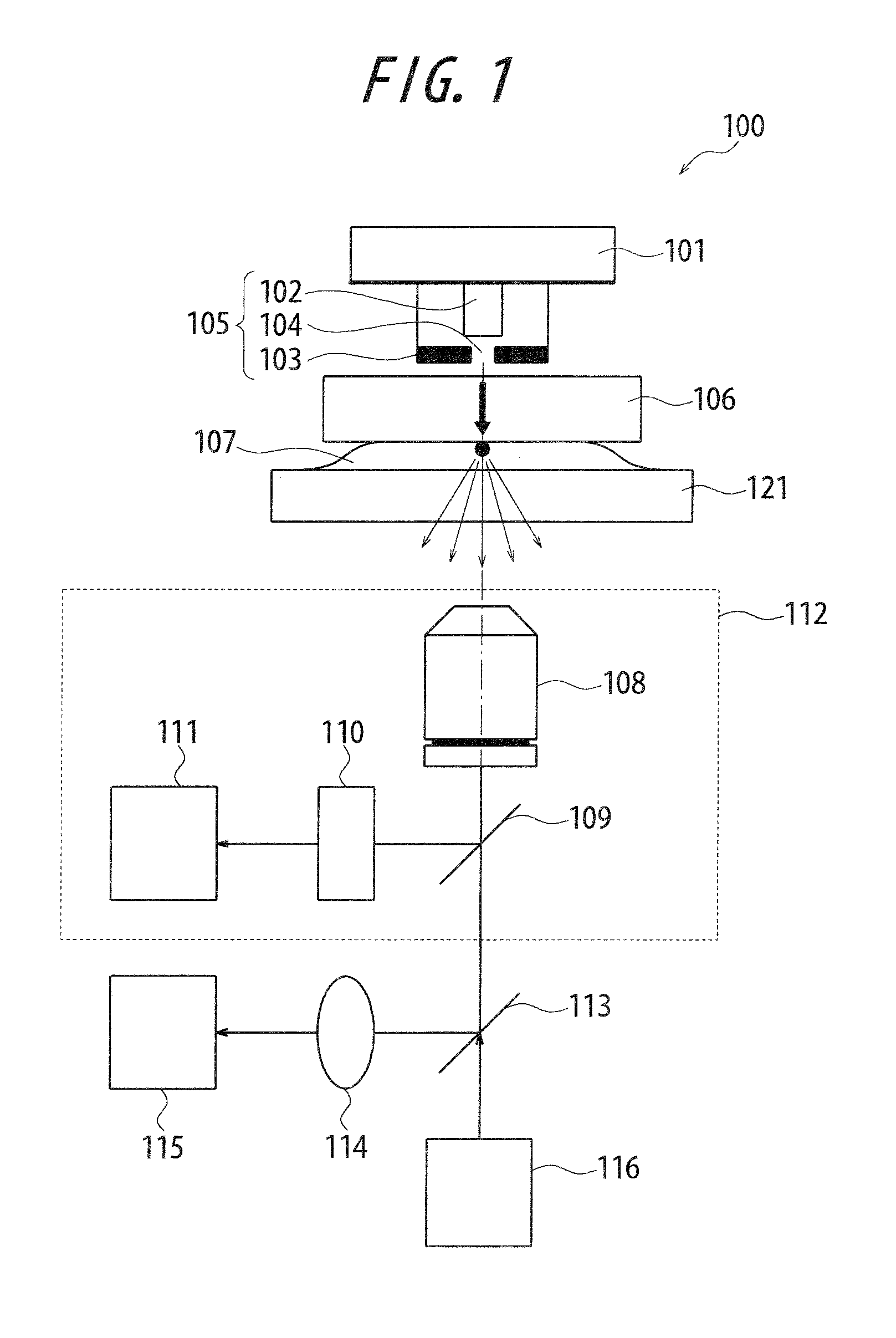
[0074]FIG. 1 illustrates a system configuration of a near-field optical microscope according to a first embodiment of the present invention. The near-field optical microscope 100 includes a scanning part 101, a near-field light source 105, an ultrahigh-wavenumber transmitting medium 106, a light receiving part 112, a half mirror 113, an imaging lens 114, an imaging element 115, and an optical microscope illuminating part (hereinafter, referred to as OM illuminating part) 116. The ultrahigh-wavenumber transmitting medium 106 is disposed between a sample 107 and an aperture 104. The light receiving part 112 includes an objective 108, a dichroic mirror 109, a filter 110, and a light receiving element 111.

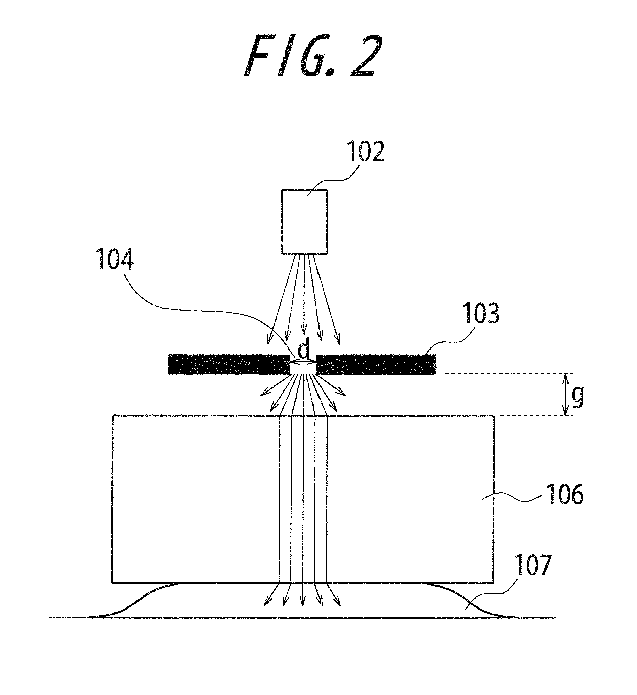
[0075]A light shielding member 103 is irradiated with light (with a wavelength Eλ) emitted from a light source 102 forming a light irradiating part for emitting illumination light toward the sample 107. The light shielding member 103 has the aperture 104 smaller than the wavelength of ...

second embodiment

[0113]FIG. 18 illustrates an example of a system configuration of a near-field optical microscope according to a second embodiment of the present invention. In FIG. 18, the near-field optical microscope 200 includes an optical system including a light source 202 forming a light irradiating part for emitting illumination light toward the sample 201 and an objective 203, a near-field optical probe 204, and an ultrahigh-wavenumber transmitting medium 205 disposed between a sample 201 and the near-field optical probe 204 including a microstructure 223. It should be noted that the near-field optical microscope 200 employs the optical probe 204, and may also be referred to as optical probe microscope.

[0114]The irradiation light emitted from the light source 202 passes through a collimating lens 206 to be converted into substantially parallel light, and then passes through a first half mirror 207 to be focused onto an observation region on the sample 201 by the objective 203. As a result, ...

third embodiment

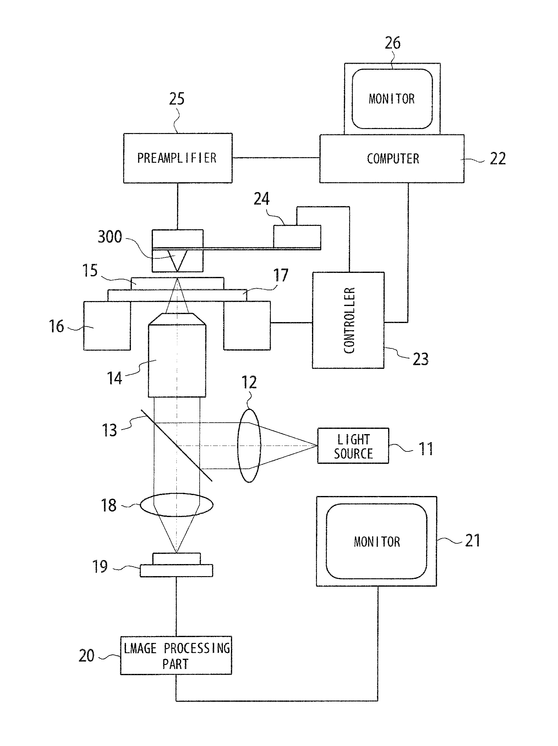
[0138]FIG. 26 is a schematic diagram illustrating a system configuration of a scanning near-field optical microscope which uses a near-field optical probe according to a third embodiment. The scanning near-field optical microscope includes an optical microscope and a near-field optical microscope. Illumination light emitted from a light source 11 passes through a collimating lens 12 to be converted into substantially parallel light (planar wave), which is then reflected by abeam splitter 13 to be focused by an objective 14 onto a sample 15 such as a living cell. As a result, response light is radiated from a predetermined position on the sample 15. The sample 15 is placed on a sample stage 17 which is driven one-dimensionally or two dimensionally by a sample stage actuator 16.

[0139]The response light radiated from the sample 15 includes reflected light, scattered light, diffracted light, or light emitted by the fluorochrome in the sample 15 upon excitation by the illumination light,...


PUM


Abstract

Provided is a scanning near-field optical microscope capable of obtaining in a highly sensitive manner, optical information having a spatial frequency higher than a spatial frequency corresponding to a wavelength of irradiation light. A scanning near-field optical microscope 100 according to the present invention includes: a light irradiating part 102 for emitting illumination light toward a sample 107; a light receiving part 112 for receiving light; a microstructure for generating or selectively transmitting near-field light, the microstructure being disposed on at least one of an emission side of the light irradiating part 102 and an incident side of the light receiving part 112; and an ultrahigh-wavenumber transmitting medium 108 for transmitting near-field light, the ultrahigh-wavenumber transmitting medium exhibiting anisotropy in permittivity or permeability.

Description

CROSS REFERENCE TO RELATED APPLICATION[0001]The present application claims priority to Japanese Patent Application No. 2011-76697 filed on Mar. 30, 2011, Japanese Patent Application No. 2010-143193 filed on Jun. 23, 2010, and Japanese Patent Application No, 2010-143197 filed on Jun. 23, 2010, the entire disclosure of which is fully incorporated herein by reference.BACKGROUND OF THE INVENTION[0002]The present invention relates to a near-field optical microscope, a near-field optical probe, and a sample observation method.RELATED ART[0003]In a scanning near-field optical microscope, a near-field optical probe having a minute aperture has been conventionally used (see, for example, JP 59-121310 A). A near-field optical probe of this type includes a quartz rod having a pointed tip, and an aperture which is formed at the tip through metal coating covering the entire crystal rod except for the tip thereof, the aperture being smaller than the wavelength of light. The near-field optical pro...

Claims


Application Information

Patent Timeline
IPC IPC(8): G01Q60/22G02B21/06G01Q60/18H01J3/14
CPCB82Y20/00G01Q60/22B82Y35/00
Inventor KARAKI, KOICHINISHIOKA, KIMIHIKOSASAKI, YASUOTSUKAGOSHI, TAKUYAAJIKI, YOSHIHARUSHIMOYAMA, ISAOMATSUMOTO, KIYOSHIKAN, TETSUROTAKEI, YUSUKENODA, KENTARO
Owner OLYMPUS CORP
Why Eureka
Try Eureka