Laser Based Image Display System

Inactive Publication Date: 2012-01-05
LIGHT BLUE OPTICS
View PDF4 Cites 128 Cited by
  • Summary
  • Abstract
  • Description
  • Claims
  • Application Information

AI Technical Summary

Benefits of technology

[0044]In embodiments a hologram generation processor driving the SLM with hologram data for the desired, displayed image converts input image data to target image data prior to converting to a hologram and compensates for the different scaling of the colour components of the multicolour projected image for replication when calculating this target image. Such

Problems solved by technology

This approach a see-through device but the manufacturing process required is rather complex and the optical efficiency is relatively low.
However the manufacturing costs of such an arrangement are again high and the optical efficiency is believed to be relatively low.
Special problems are presented by

Method used


Image

  • Laser Based Image Display System
  • Laser Based Image Display System
  • Laser Based Image Display System

Examples


Example

[0059]This invention relates to optical techniques for replicating an image, in particular for expanding the exit pupil of a head-up display.

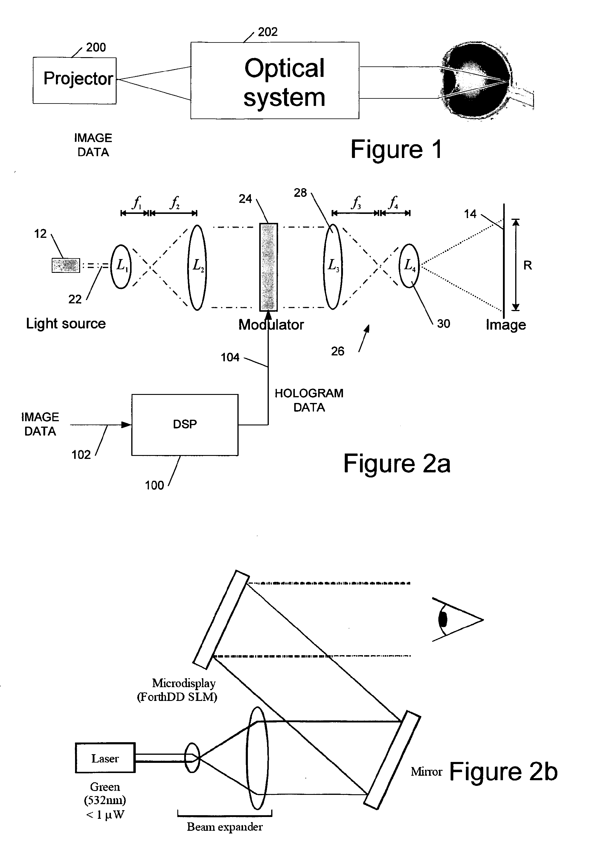
[0060]FIG. 1 shows a general arrangement of an example of a head-up display providing a virtual image, the system comprising a projector 200, used as the image source, and an optical system 202 providing a virtual image display at the viewer's retina.

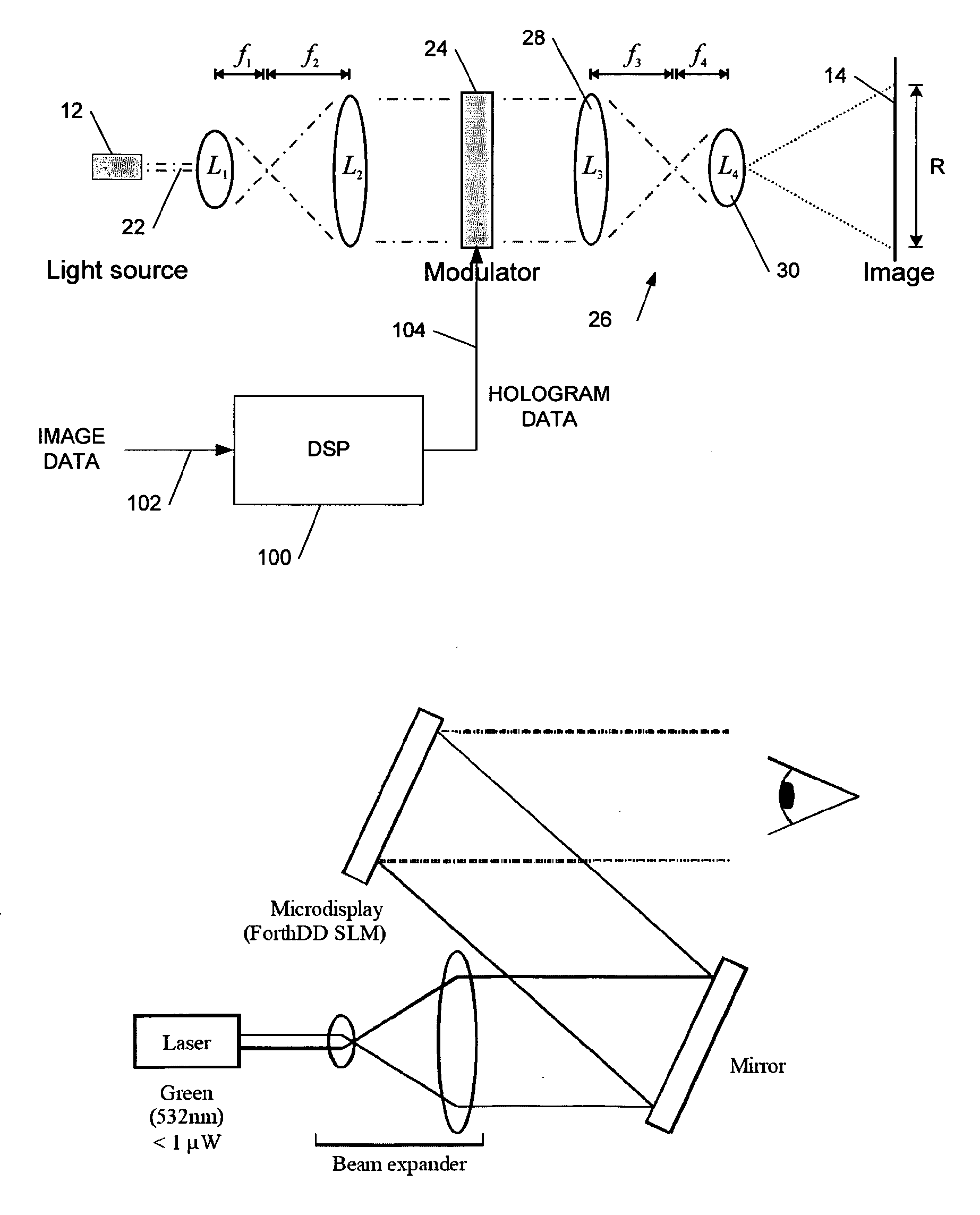
[0061]FIG. 2a shows a simple example of a holographic image projection system which may be employed in a head-up display of the type shown in FIG. 1. The system comprises a laser diode 20 which provides substantially collimated light 22 to a spatial light modulator (SLM) 24, via lenses L1 and L2 which form a beam-expansion pair so that the light covers the modulator. The light is phase modulated by a hologram displayed on the SLM and provided to a demagnifying optical system 26, as illustrated comprising a pair of lenses (L3, L4) 28, 30 with respective focal lengths f3, f4, f43, spaced apart at dis...


PUM


Abstract

We describe optical techniques for replicating an image to expand the exit pupil of a head-up laser-based image display system. The system includes image replication optics to replicate an image carried by a substantially collimated beam, the image replication optics comprising a pair of substantially planar reflecting optical surfaces defining substantially parallel planes spaced apart in a direction perpendicular to the parallel planes. The system is configured to launch the collimated beam into a region between the parallel planes such that the reflecting optical surfaces waveguide the beam between the surfaces in a plurality of successive reflections at front and rear optical surfaces. The front optical surface is configured to transmit a proportion of the collimated beam when reflecting the beam such that at each reflection of the collimated beam at the front optical surface a replica of the image is output from the image replication optics.

Description

CROSS REFERENCE TO RELATED APPLICATION[0001]This application claims priority to PCT Application No. PCT / GB2010 / 050251 entitled “Laser Based Image Display System” and filed Feb. 16, 2010, which itself claims priority to Great Britain Patent Application No. GB0902468.8 filed Feb. 16, 2009. The entirety of each of the aforementioned applications is incorporated herein by reference for all purposes.BACKGROUND OF THE INVENTION[0002]This invention relates to optical techniques for replicating an image, in particular for expanding the exit pupil of a head-up display.[0003]We have previously described techniques for displaying an image holographically—see, for example, WO 2005 / 059660 (Noise Suppression Using One Step Phase Retrieval), WO 2006 / 134398 (Hardware for OSPR), WO 2007 / 031797 (Adaptive Noise Cancellation Techniques), WO 2007 / 110668 (Lens Encoding), WO 2007 / 141567 (Colour Image Display), WO 2008 / 120015 (Head Up Displays), and GB0811729.3 (Head Up Displays). These are all hereby inco...

Claims


Application Information

Patent Timeline
IPC IPC(8): G03H1/08G02B27/28G03H1/22G02B27/01
CPCG02B27/0081G02B27/0172G03H1/22G03H2001/2271G03H2001/2239G03H2001/2242G03H1/2205G02B6/00G02B27/01G03H1/08
Inventor LACOSTE, LILIANCORBETT, ALEXANDER DAVIDSTINDT, DOMINIK
Owner LIGHT BLUE OPTICS
Why Eureka
Try Eureka