Grating production method, diffraction grating device, and radiation imaging apparatus
a technology of diffraction grating and production method, which is applied in the direction of imaging devices, manufacturing tools, instruments, etc., can solve the problems of difficult to arrange the small grating plates on the curve surface, limited wafer processing capacity in the second diffraction grating,
- Summary
- Abstract
- Description
- Claims
- Application Information
AI Technical Summary
Benefits of technology
Problems solved by technology
Method used
Image
Examples
1st embodiment
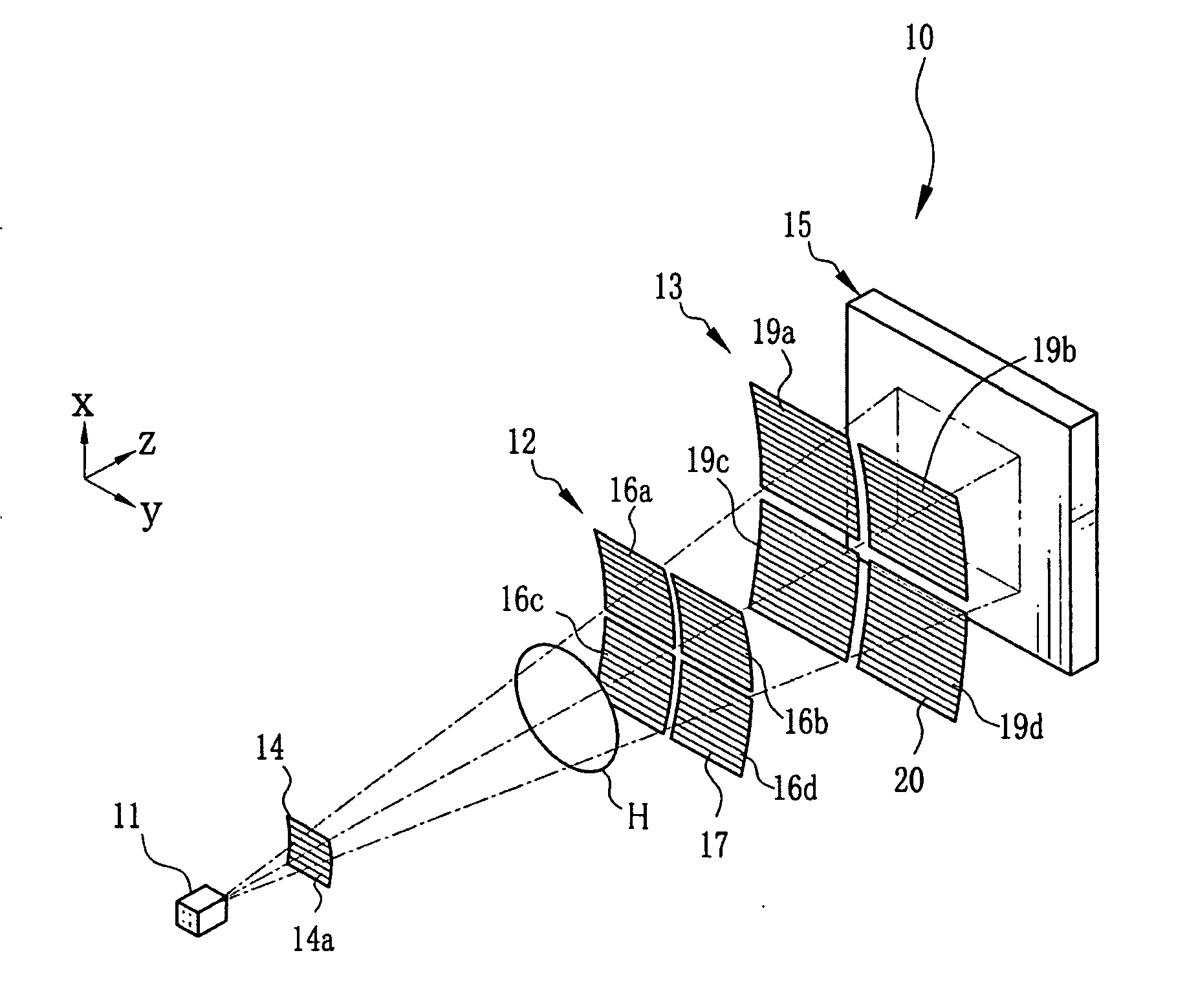
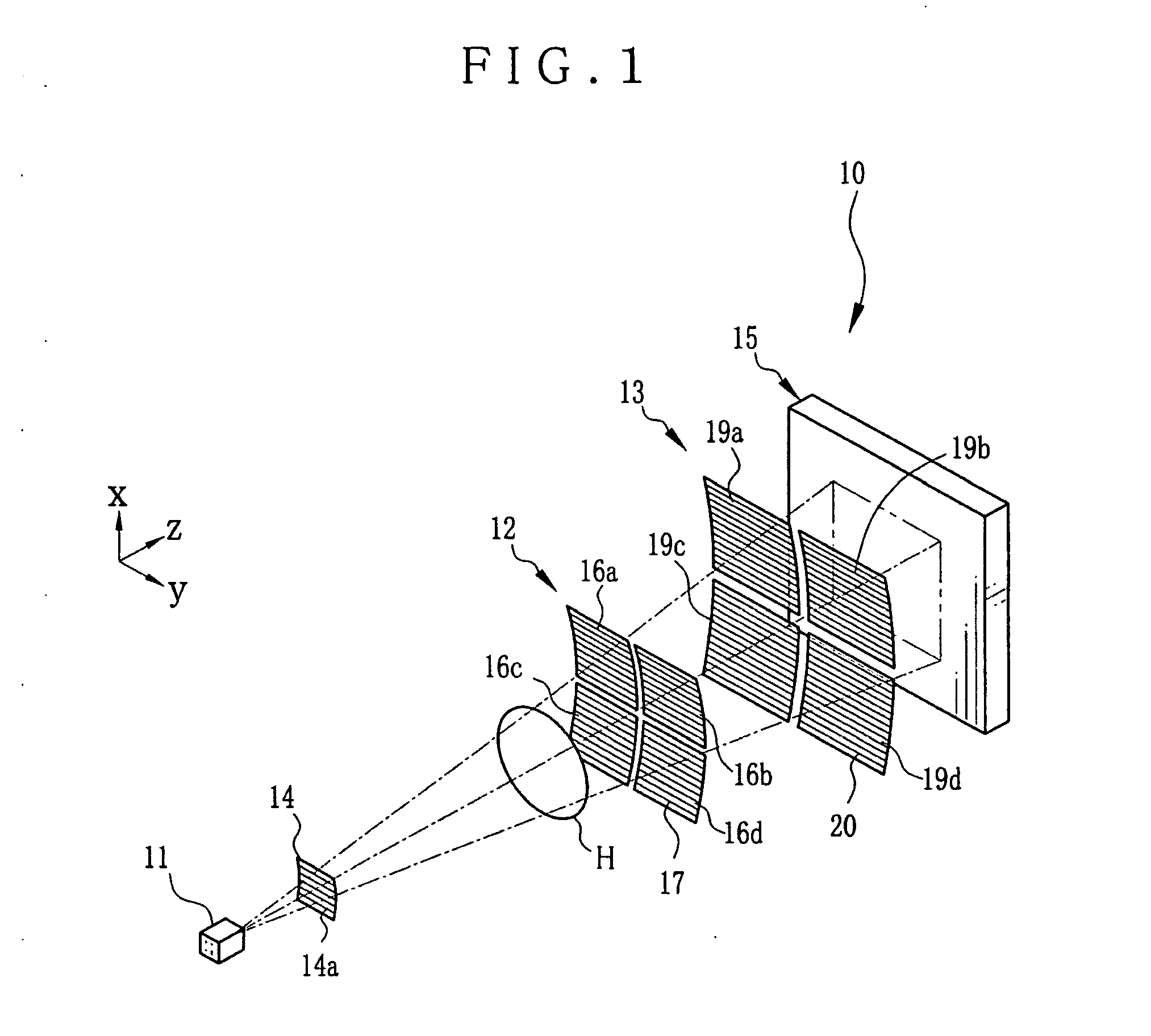
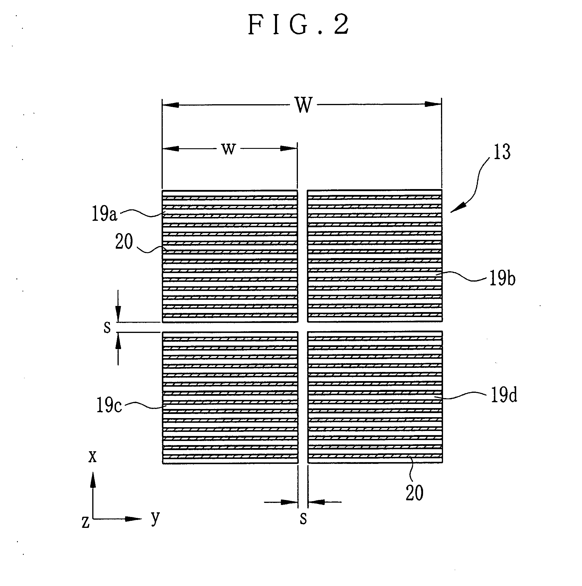
[0079]The second diffraction grating device 13 and its production method according to the invention are hereinafter described. In FIGS. 5 and 6, the second diffraction grating device 13 includes a composite grating 33, a concave holding plate 34 or covering plate or stage, a convex holding plate 35 or covering plate or stage, and clamping caps 36 and 37 for sealing and reinforcement. The composite grating 33 includes the small grating plates 19a-19d, and a first support plate 31 and a second support plate 32 for sandwiching the small grating plates 19a-19d. The concave and convex holding plates 34 and 35 sandwich the composite grating 33 in the z-direction in a curved form. The clamping caps 36 and 37 are fitted on outer sides of the concave and convex holding plates 34 and 35 in the x-direction. A concave surface 34a and a convex surface 35a are formed with respectively opposed surfaces of the concave and convex holding plates 34 and 35 as first and second holding plates, for sandw...
2nd embodiment
[0091]In contrast with the concave and convex holding plates 34 and 35 in the first embodiment, a second diffraction grating device 45 of FIGS. 8 and 9 includes an opening 34b in the concave holding plate 34 and an opening 35b in the convex holding plate 35 for the small grating plates 19a-19d. In short, the concave and convex holding plates 34 and 35 can be formed in a frame shape. This structure is effective in increasing the X-ray transparency.
[0092]FIGS. 10A-10E illustrate production of the second diffraction grating device 45. For the production of the composite grating 33, the first embodiment is repeated. In FIG. 10A, an additional support pad 47 includes a second concave surface 47a for entry in the opening 34b of the concave holding plate 34. In an initial step, the composite grating 33 is squeezed between the second concave surface 47a and the suction pad 42. The second concave surface 47a is so concave as to connect smoothly with the concave surface 34a when the concave h...
3rd embodiment
[0097]Furthermore, reinforcing portions can be formed with small grating plates for higher mechanical strength on their periphery by use of silicon. In FIG. 11, L-shaped reinforcing portions 50 are formed with two of the side lines of each of the small grating plates 19a-19d in the four-plate structure. In short, the reinforcing portions 50 are arranged on the periphery of the entirety of the combination of the small grating plates 19a-19d. See FIG. 12. To sandwich the composite grating 33 between the concave and convex holding plates 34 and 35, the reinforcing portions 50 are effective in preventing collapse of the periphery of the small grating plates 19a-19d with pressure of the concave and convex holding plates 34 and 35. It is possible to utilize even edge portions of the small grating plates 19a-19d optically as diffraction gratings.
[0098]In FIG. 13, a reinforcing portion 52 of another example is illustrated, and is in an L shape where silicon and gold (Au) are positioned alte...
PUM
| Property | Measurement | Unit |
|---|---|---|
| Area | aaaaa | aaaaa |
| Transparency | aaaaa | aaaaa |
Abstract
Description
Claims
Application Information
 - R&D
- Intellectual Property
- Life Sciences
- Materials
- Tech Scout
- Unparalleled Data Quality
- Higher Quality Content
- 60% Fewer Hallucinations
Browse by: Latest US Patents, China's latest patents, Technical Efficacy Thesaurus, Application Domain, Technology Topic, Popular Technical Reports.
© 2025 PatSnap. All rights reserved.Legal|Privacy policy|Modern Slavery Act Transparency Statement|Sitemap|About US| Contact US: help@patsnap.com


