Fine particles

Active Publication Date: 2012-01-05
NCC NANO LLC
View PDF3 Cites 6 Cited by
  • Summary
  • Abstract
  • Description
  • Claims
  • Application Information

AI Technical Summary

Benefits of technology

[0051]In some examples the coating material is heated prior to injection. Heating the coating material reduces viscosity facilitating conversion into a fine spray.
[0052]Subsequent to coating the fine particles are recovered using organic solvents which are then evaporated from the particles. The resulting product is a free-flowing powder of fine particles of the invention. Alternatively, the removal of the organic solvent may be after the coating of a surface with the fine particles, in such examples solvent removal leaves a layer of fine

Problems solved by technology

A common problem in the preparation of fine particles is their tendency to agglomerate, this is generally believed to be as a result of their high surface area to volume ratio which causes the particles to have a relatively high surface energy.
This places limitations upon the presentation of the fine particles to any medium with which they are to interact.
As a result, the formation of liquid suspensions in this way can result in fine particle

Method used


Image

  • Fine particles
  • Fine particles
  • Fine particles

Examples


Example

Example 1

Synthesis of Fine Particles Using Injection Techniques

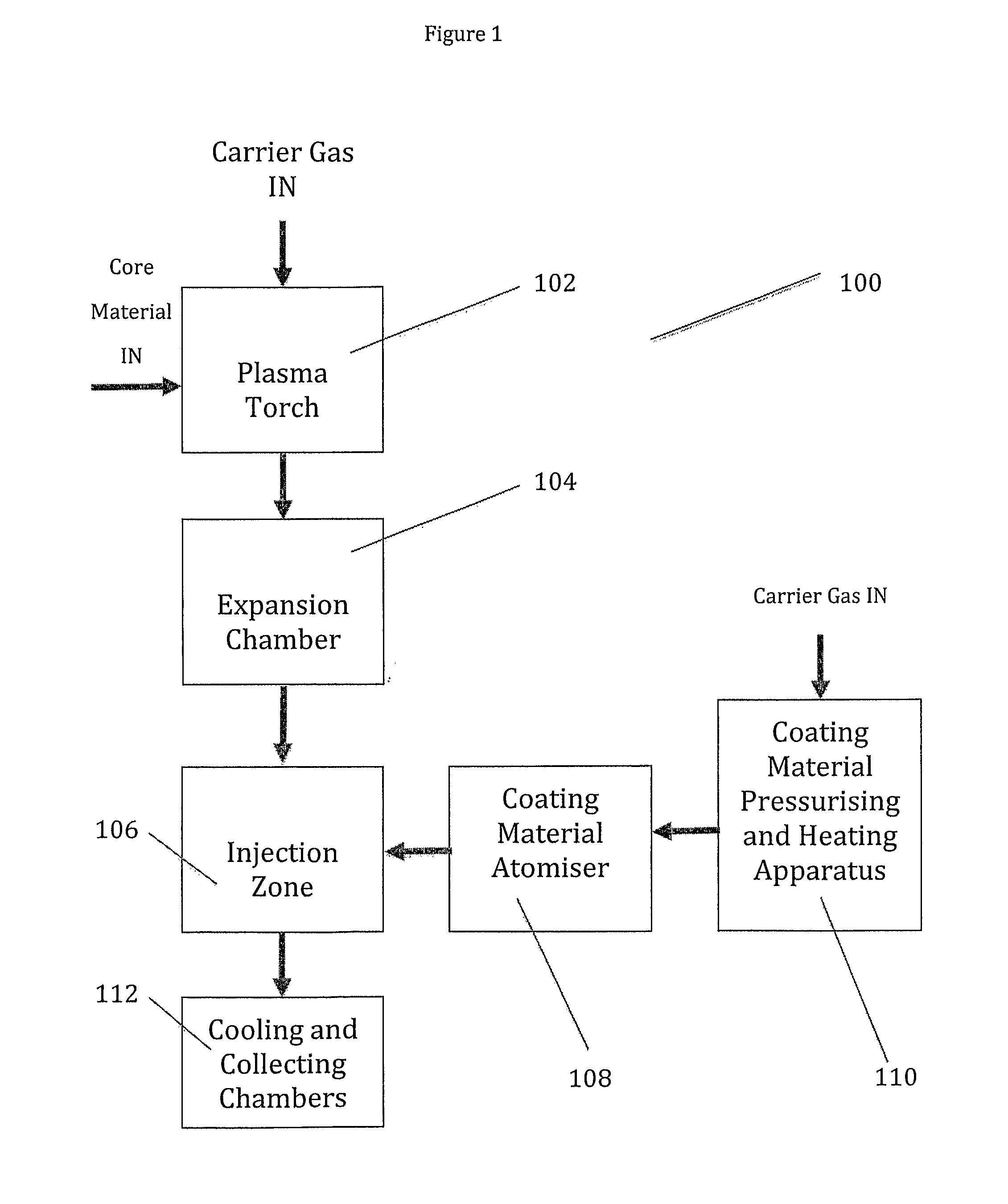
[0118]Powdered copper was injected into the apparatus of FIG. 1 through an alumina ring.

[0119]Oleic acid was warmed to about 50° C. and injected into the apparatus in a stream of argon. Heating the oleic acid reduced its viscosity. The acid was injected into the plasma stream at a flow rate of 25 ml / minute just above the quench ring, where the temperature was high enough to vaporise the acid, but low enough that decomposition would not occur.

[0120]After collection of the fine particles the reactor was cooled and inspected. This inspection showed that clean vaporisation of the core material had occurred and that there was no deposition of the core material on the walls of the chamber. This was attributed to the powder injection through the alumina ring. Whilst some deposition of the fine particles was observed on the filter elements, this could be removed and recovered using water or isopropanol. The recovery of agglomera...

Example

Example 2

Characterisation of the Fine Particles of FIG. 1

[0122]SEM and STEM images were recorded for copper fine particles produced using the apparatus of FIG. 1 with and without an oleic acid coating.

[0123]In SEM an electron beam scans a surface and reproduces the image measured at the detector (for back-scattered (elastic) or secondary electrons, also X-rays which can give chemical mapping of the surface) onto a screen scanned in the same manner, to give a surface image at higher magnification than is possible using the frequency of light. STEM is a modification of SEM, where the apparatus is fitted with a second detector below the sample stage so that it may also be used to collect and detect electrons that pass through the sample, making it a Transmission Electron Microscope (TEM) for such samples as are sufficiently thin or which pose low resistance to the electrons for any to pass through to the detector.

[0124]The images with the coating (FIGS. 6 to 10) show copper nanoparticl...

Example

Example 3

Protection of Core Material from Oxidation

[0126]Two XRD spectra were run on a copper core coated with oleic acid. These are shown in FIG. 14 (day 0—black, day 30—grey). As can be seen, the oxidation of the copper is negligible as the height of the Cu(0) peak has not varied. Accordingly, the oleic acid coating has protected the copper core from oxidation.

[0127]FIG. 15 shows two XRD spectra run on a copper core coated with PVP (day 0—black, day 30—grey). As with the oleic acid core above, the height of the Cu(0) peak has not varied, and hence the copper core has been protected from oxidation by the PVP coating.


PUM

PropertyMeasurementUnit
Diameteraaaaaaaaaa
Temperatureaaaaaaaaaa
Pressureaaaaaaaaaa

Abstract

A fine particle comprising a core and a coating, wherein the coating comprises a substantially monomolecular layer of organic molecules. The fine particle being produced by a process comprising introducing a core material into a plasma stream, thereby vapourising some or all of the core material; cooling the core material downstream from where the core material was introduced thereby creating particles of the core material; and coating the particles of the core material with organic molecules in an injection zone, wherein the injection zone is downstream of a region where the particles of core material are formed, or wherein the cooled particles of core material are coated with organic molecules in a coating chamber by applying a liquid coating material and/or a solution of coating material to the core material; where in the coating chamber is downstream of a region wherein the particles of core material are formed.

Description

FIELD OF THE INVENTION[0001]The invention relates to fine particles, to an apparatus for use in this process, and to a process for preparing fine particles. In particular, the invention relates to fine particles comprising a core and coating, and to a process and apparatus for preparing these.BACKGROUND OF THE INVENTION[0002]A common problem in the preparation of fine particles is their tendency to agglomerate, this is generally believed to be as a result of their high surface area to volume ratio which causes the particles to have a relatively high surface energy. It has been speculated that the agglomeration could be as a result of electrostatic forces between the particles, cold sintering, or van der Waals interactions. The result of this agglomeration is that fine particles are generally found as clusters, platelets or strings of the fine particles, and not as isolated fine particulate matter.[0003]It would be advantageous to provide fine particles which are not agglomerated as ...

Claims


Application Information

Patent Timeline
IPC IPC(8): H05H1/26C23C16/50B22F1/00B22F1/054B22F1/102
CPCB22F1/0018B22F1/0062B22F9/12B22F2999/00B82Y30/00B22F2998/00B22F2202/13B22F1/0022B22F1/102B22F1/054B22F1/00B22F1/0545B22F9/14
Inventor GODFREY, ALASTAIR BRYANKONG, ADAM
Owner NCC NANO LLC
Why Eureka
Try Eureka