Beam-Induced Deposition at Cryogenic Temperatures

a beam-induced deposition and cryogenic temperature technology, applied in the direction of pretreatment surfaces, coatings, metal material coating processes, etc., can solve the problems of unreliable bonding, cryogenic temperature not working well, and normal ebid/ibid processes not working

Active Publication Date: 2012-01-05
FEI CO
View PDF4 Cites 38 Cited by
  • Summary
  • Abstract
  • Description
  • Claims
  • Application Information

AI Technical Summary

Benefits of technology

[0010]The foregoing has outlined rather broadly the features and technical advantages of the present invention in order that the detailed description of the invention that follows may be better understood. Additional features and advantages of the invention will be described hereinafter. It should be appreciated by those skilled in the art that the conception and specific embodiments disclosed may be readily utilized as a basis for modifying or designing other structures for carrying out the same purposes of the present invention. It should also be realized by those skilled in the art that such equivalent constructions do not depart from the spirit and scope of the invention as set forth in the appended claims.

Problems solved by technology
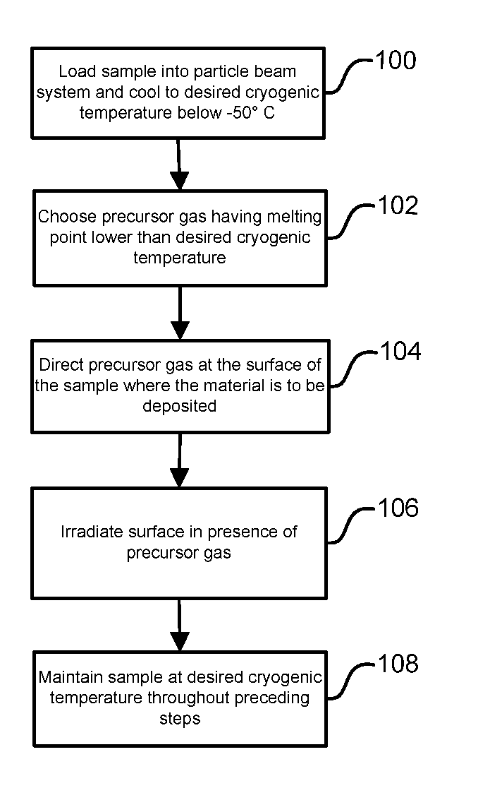
A disadvantage of known beam induced deposition methods is that they do not work well at cryogenic temperatures (below −50° C., more specifically below −130° C.).
At cryogenic temperatures, normal EBID / IBID processes do not work.
This results in a thickening frozen layer of gas molecules covering the surface, making it difficult for the charged particle beam to cause dissociation of the precursor molecules and preventing any deposited material from bonding to the substrate surface resulting in an unreliable bond when used to attach a sample to a manipulator or holder.
Further, the typical “volatile by-products” also freeze onto the surface at these low temperatures and may also disturb the formation of the bond.
Also, when the sample is at a later stage brought up to a temperature above the melting, sublimation or boiling point of the, then suddenly volatile, by-products, can lead to damage of the intended structure.
As a result, it will be hard or impossible to write patterned thin film surfaces on the sample.
This is not practical for preparation of TEM samples of biological materials since the samples must be maintained below the vitrification temperature to avoid damaging the biological sample.
Further, the method described by Bozso is limited to depositing silicon, silicon nitride, silicon oxide, and silicon oxinitride films onto silicon.
The material deposition rates would thus be impractical for sample welding or even for forming thicker / larger protective layers.

Method used


Image

  • Beam-Induced Deposition at Cryogenic Temperatures
  • Beam-Induced Deposition at Cryogenic Temperatures
  • Beam-Induced Deposition at Cryogenic Temperatures

Examples


Embodiment Construction

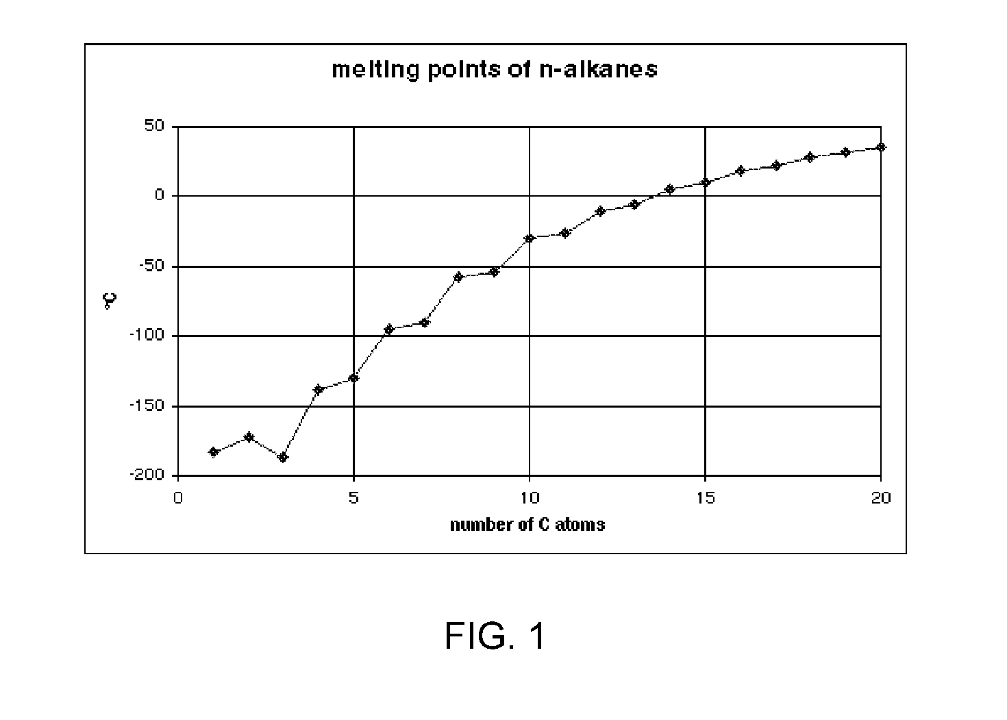
[0020]A disadvantage of known beam induced deposition methods is that they do not work well at cryogenic temperatures, while a number of applications, including the preparation of TEM samples of biological materials, require samples to be maintained at those cryogenic temperatures, generally from −50° C. to −130° C. While beam systems with cryogenic chambers are known in the art, maintaining the sample chamber at cryogenic temperatures creates problems for EBID or IBID in the system, as the precursor gases tend to freeze to the TEM sample chamber. At temperatures below −50° C. most known precursor gases suitable for beam-induced deposition freeze onto the substrate surface and the normal EBID / IBID processes do not work.

[0021]At the normal operating temperatures for beam-induced deposition, most known precursor gases have a sticking coefficient between 0.5 and 0.8. “Sticking coefficient” describes the ratio of the number of adsorbate molecules (or atoms) that adsorb, or “stick,” to a...


PUM

PropertyMeasurementUnit
cryogenic temperatureaaaaaaaaaa
melting pointaaaaaaaaaa
cryogenic temperatureaaaaaaaaaa

Abstract

A method of depositing material onto a substrate at cryogenic temperatures using beam-induced deposition. A precursor gas is chosen from a group of compounds having a melting point that is lower than the cryogenic temperature of the substrate. Preferably the precursor gas is chosen from a group of compounds having a sticking coefficient that is between 0.5 and 0.8 at the desired cryogenic temperature. This will result in the precursor gas reaching equilibrium between precursor molecules adsorbed onto the substrate surface and precursor gas molecules desorbing from the substrate surface at the desired cryogenic temperature. Suitable precursor gases can comprise alkanes, alkenes, or alkynes. At a cryogenic temperature of between −50° C. and −85° C., hexane can be used as a precursor gas to deposit material; at a cryogenic temperature of between −50° C. and −180° C., propane can be used as a precursor gas.

Description

TECHNICAL FIELD OF THE INVENTION[0001]The invention relates to electron and ion beam induced deposition, and more particularly to beam-induced deposition at cryogenic temperatures.BACKGROUND OF THE INVENTION[0002]In the prior art, it is known to deposit a material onto a substrate via electron beam induced deposition (EBID) and ion beam induced deposition (IBID). According to the known method, a substrate is placed in the evacuable specimen chamber of a charged particle beam apparatus—typically either an electron beam (E-beam) system or a focused ion beam (FIB) system. The charged particle (or other) beam is applied to the substrate surface in the presence of a deposition gas, often referred to as a precursor gas. A layer of the precursor gas adsorbs to the surface of the work piece. The thickness of the layer is governed by the balance of adsorption and desorption of the gas molecules on the substrate surface, which in turn depends on, for example, the partial gas pressure (determi...

Claims


Application Information

Patent Timeline
Patent Type & Authority Applications(United States)
IPC IPC(8): B05D3/06
CPCC23C16/26C23C16/486C23C16/463
Inventor MULDERS, JOHANNES JACOBUS LAMBERTUSFRANCISCUS TROMPENAARS, PETRUS HUBERTUS
Owner FEI CO
Why Eureka
Try Eureka