Thermal power plant using low-grade coal as fuel

Inactive Publication Date: 2012-01-12
KYUSHU ELECTRIC POWER CO INC +1
View PDF14 Cites 16 Cited by
  • Summary
  • Abstract
  • Description
  • Claims
  • Application Information

AI Technical Summary

Benefits of technology

[0083]The thermal power plant using low-grade coal as fuel according to the present

Problems solved by technology

Because low-grade coal has a high moisture content, even if it is pulverized into particles small enough that the coal can be combusted and used as fuel for a boiler, heat loss (i.e

Method used


Image

  • Thermal power plant using low-grade coal as fuel
  • Thermal power plant using low-grade coal as fuel
  • Thermal power plant using low-grade coal as fuel

Examples


first embodiment

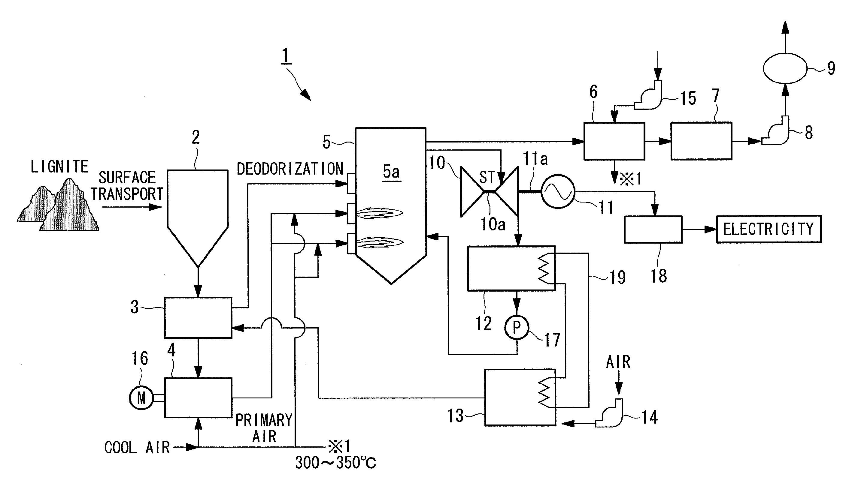
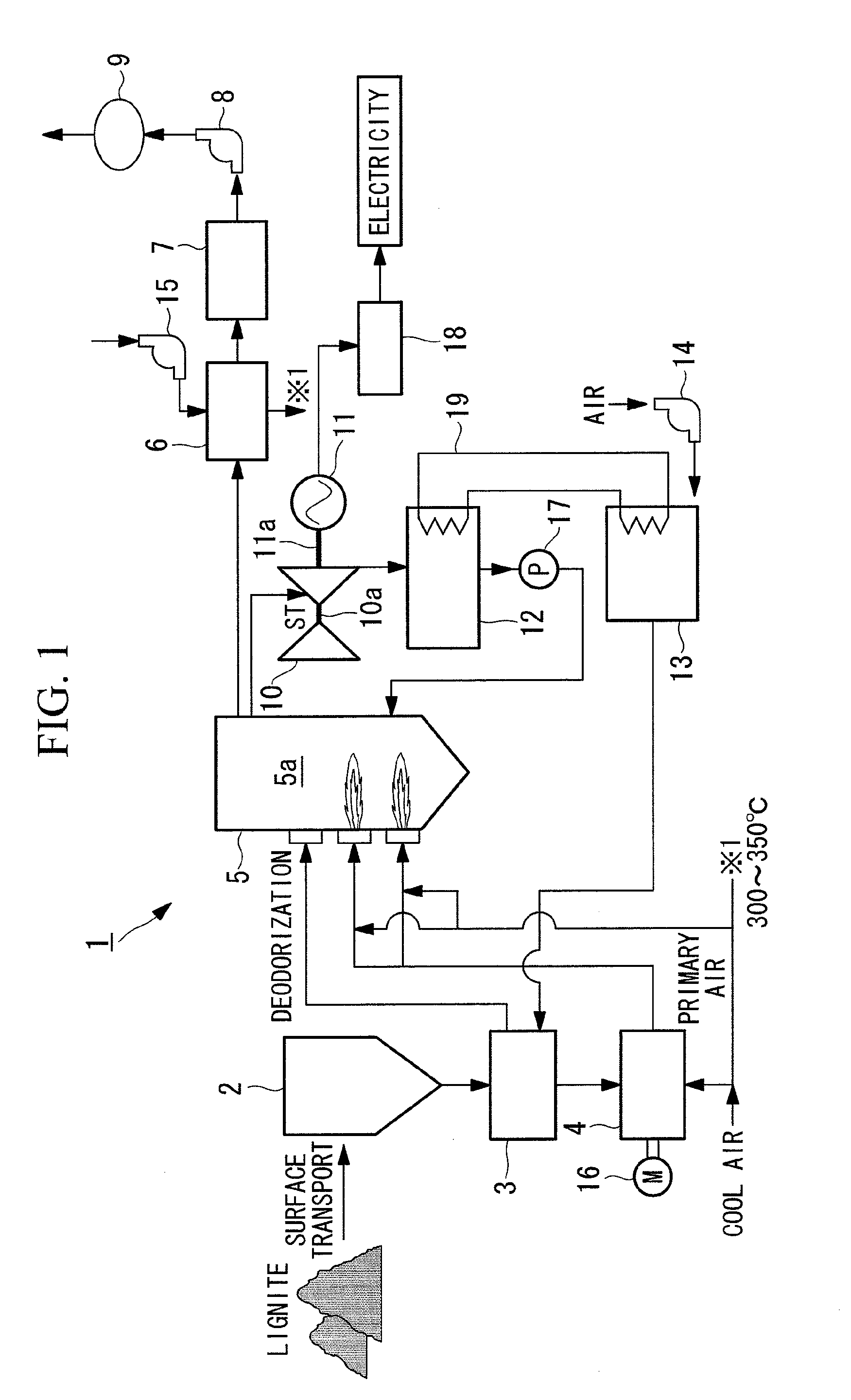
[0105]a thermal power plant that uses low-grade coal as fuel (referred to as “lignite-fired thermal power plant” hereinafter) according to the present invention will be described below with reference to FIG. 1.

[0106]FIG. 1 schematically illustrates the configuration of the lignite-fired thermal power plant according to this embodiment.

[0107]As shown in FIG. 1, a lignite-fired thermal power plant 1 according to this embodiment mainly includes a storage silo 2, a drying device 3, a lignite mill 4, a boiler 5, an air preheater 6, an electrostatic precipitator 7, an induced draft fan 8, a smokestack 9, a steam turbine 10, a generator 11, a condenser (steam condenser) 12, and a drying-gas heater 13.

[0108]The storage silo 2 is a so-called coal bunker that temporarily stores (retains) lignite (raw lignite) that has been transported from a coal storage by a truck, a belt conveyor, or the like (not shown).

[0109]The drying device 3 removes moisture from (or dries) the lignite (raw lignite), w...

second embodiment

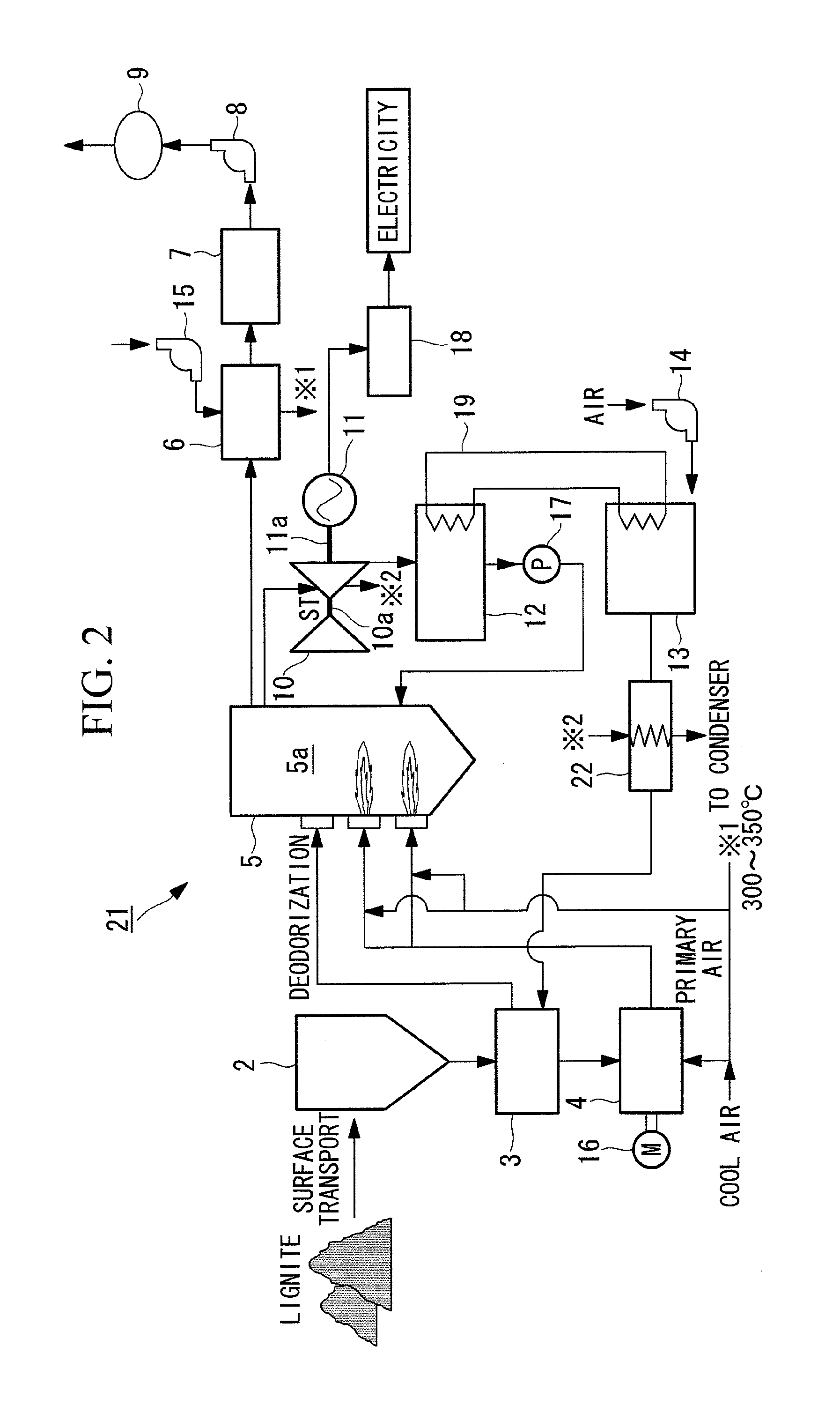
[0117]a lignite-fired thermal power plant according to the present invention will now be described with reference to FIG. 2.

[0118]FIG. 2 schematically illustrates the configuration of the lignite-fired thermal power plant according to this embodiment.

[0119]A lignite-fired thermal power plant 21 according to this embodiment differs from that in the first embodiment described above in that it includes a heater 22. Since other components are the same as those in the first embodiment described above, descriptions of these components will be omitted here.

[0120]As shown in FIG. 2, the heater 22 is provided between the drying device 3 and the drying-gas heater 13 and is a heat exchanger that further heats the warm air (primary drying air) to be supplied to the drying device 3 from the drying-gas heater 13. The heater 22 is supplied with steam extracted from an intermediate portion of the turbine section of the steam turbine 10 (e.g., an intermediate portion of a low-pressure turbine consti...

third embodiment

[0124]a lignite-fired thermal power plant according to the present invention will now be described with reference to FIG. 3.

[0125]FIG. 3 schematically illustrates the configuration of the lignite-fired thermal power plant according to this embodiment.

[0126]A lignite-fired thermal power plant 31 according to this embodiment differs from that in the second embodiment described above in that it includes a moisture meter 32 and a flow control valve 33. Since other components are the same as those in the second embodiment described above, descriptions of these components will be omitted here.

[0127]As shown in FIG. 3, the moisture meter 32 detects the moisture in the lignite to be supplied to the lignite mill 4 from the drying device 3, and the detection result obtained by the moisture meter 32 is output to a controller (not shown) and is used as data for setting the degree of opening of the flow control valve 33.

[0128]The flow control valve 33 adjusts the flow rate of the steam to be sup...


PUM


Abstract

A thermal power plant that uses low-grade coal as fuel and allows for increased thermal efficiency of the entire plant is provided. The thermal power plant includes a drying device (3) that dries the low-grade coal to be supplied to a lignite mill (coal pulverizer) (4), and a drying-gas heater (13) that heats air to be supplied to the drying device (3) so as to be used for drying the low-grade coal. A condenser (12) and the drying-gas heater (13) are connected with each other via a heat exchanger (19), and exhaust heat from the condenser (12) is used as a heat source for heating the air.

Description

TECHNICAL FIELD[0001]The present invention relates to a thermal power plant that uses low-grade coal (such as sub-bituminous coal or lignite having a moisture content that exceeds about 20 percent by mass) as fuel, and particularly, to a lignite-fired thermal power plant that uses lignite as fuel.BACKGROUND ART[0002]Because low-grade coal has a high moisture content, even if it is pulverized into particles small enough that the coal can be combusted and used as fuel for a boiler, heat loss (i.e., latent heat) caused by the moisture in combustion gas combusted within a boiler furnace increases, which is a problem in that the thermal efficiency of the entire plant decreases.[0003]In light of this, an invention for increasing the thermal efficiency of the entire plant by preliminarily drying the low-grade coal serving as fuel is disclosed in, for example, Patent Literature 1. FIG. 1 in Patent Literature 1 discloses a collision-type drying and pulverizing device.CITATION LISTPatent Lite...

Claims


Application Information

Patent Timeline
IPC IPC(8): F01K13/00F26B25/06
CPCF01K9/003F23J2217/102F23K1/04F23K2203/104F23K2201/103F23K2201/20F23K2201/101
Inventor KOYAMA, YOSHINORIYAMAMOTO, TAKASHISHINADA, OSAMUISHII, HIROMIYAMADA, HITOJIKANEKO, SHOZOTOKUDA, KIMISHIROMOCHIDA, ISAOHARADA, TATSUROU
Owner KYUSHU ELECTRIC POWER CO INC
Why Eureka
Try Eureka